SsangYong Korando II (1996-2006 year). Manual — part 279
5A-20 AUTOMATIC TRANSMISSION
SSANGYONG MY2002
PARK AND NEUTRAL
KAA5A31A

AUTOMATIC TRANSMISSION 5A-21
SSANGYONG MY2002
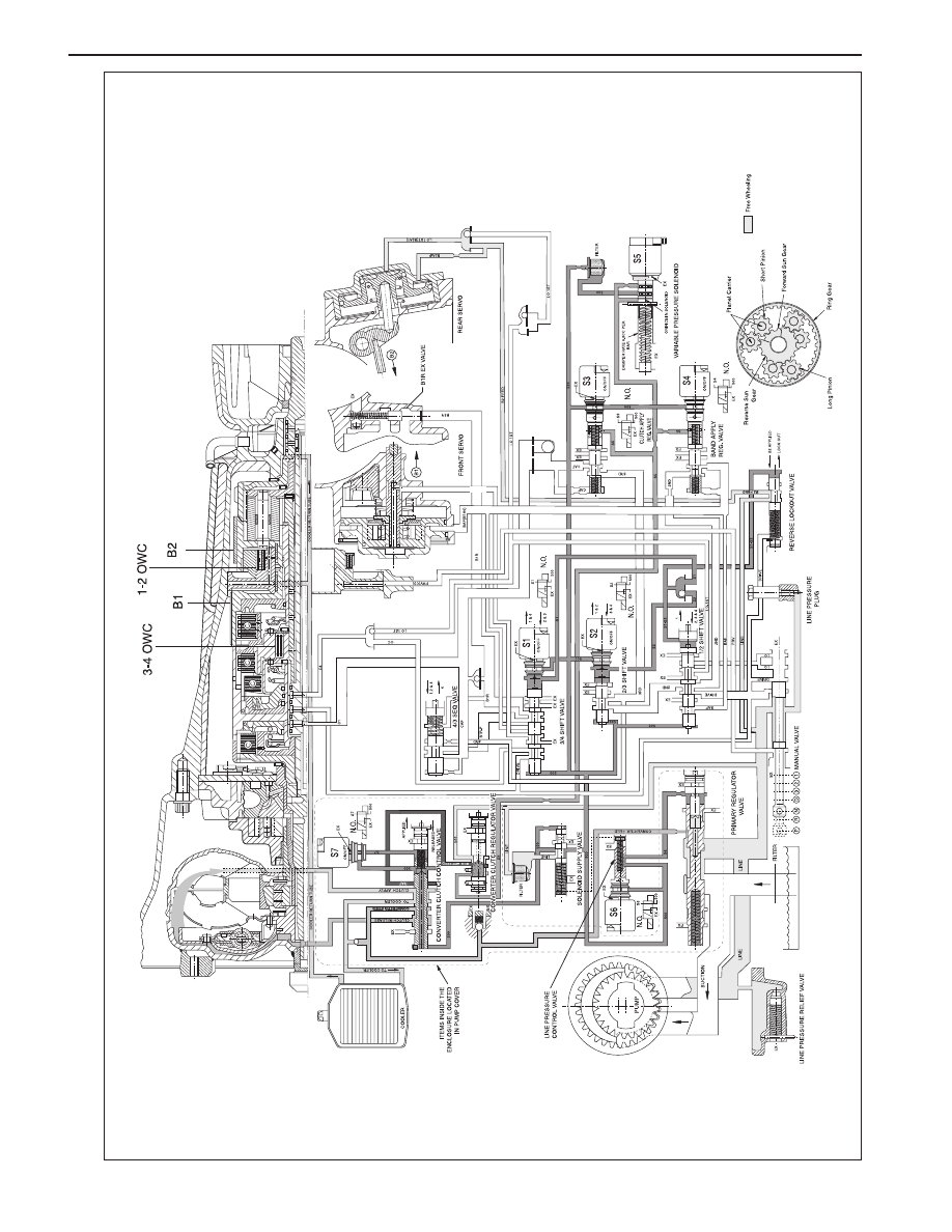
Power Flow - Park and Neutral
In Park and Neutral, there is no drive to the planetary
gear set. The rear band is applied to eliminate ‘clunk’
on engagement of the reverse gear, and to improve
the low range engagement for 4WD applications. No
other clutches or bands are applied.
In Park the transmission is mechanically locked by
engaging a case mounted pawl with teeth on the output
shaft ring gear.
Control
To maintain this arrangement in the steady state sole-
noids and valves are activated as follows:
•
Solenoids S1 and S2 are switched OFF.
•
Line (pump) pressure is applied to the Primary Regu-
lator Valve (PRV) and to the solenoid supply
pressure regulator valve.
•
The converter, oil cooler, and lubrication circuits are
charged from the primary regulator valve.
•
The line 500 circuit is charged by the solenoid
supply pressure regulator valve.
•
The S5 circuit is charged by the variable pressure
solenoid (S5).
•
Line pressure is prevented from entering the drive
circuit by the manual valve.
•
The B1 circuit and all clutch circuits are open to ex-
haust.
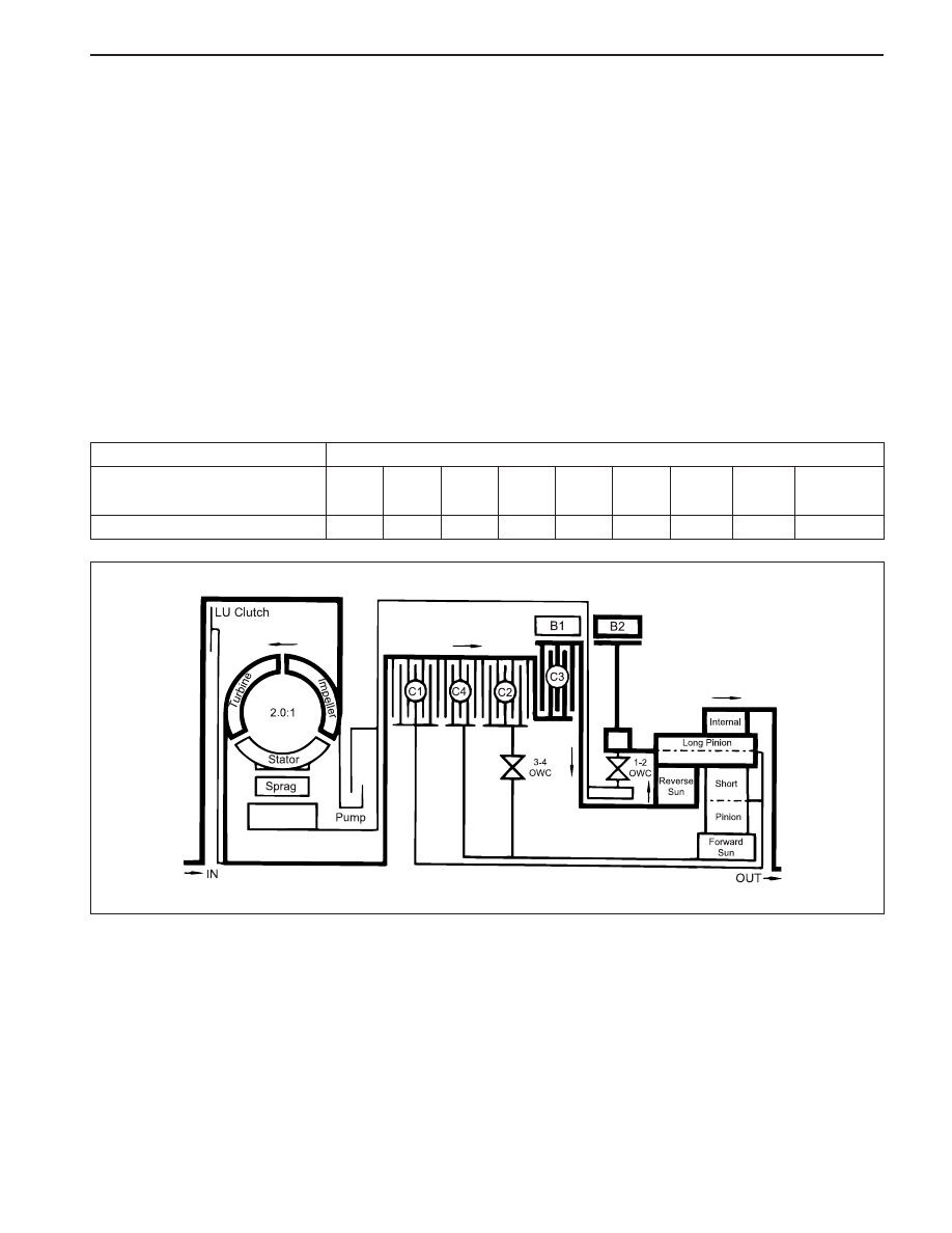
C1
-
C2
-
C3
-
C4
-
B1
-
B2
X
1-2
OWC
-
3-4
OWC
-
LU
CLUTCH
-
Gear State
Park and Neutral
ELEMENTS ENGAGED
KAA5A320

5A-22 AUTOMATIC TRANSMISSION
SSANGYONG MY2002
REVERSE
KAA5A33A
AUTOMATIC TRANSMISSION 5A-23
SSANGYONG MY2002
Power Flow - Reverse
In Reverse, transmission drive is via the input shaft
and the forward clutch cylinder to the hub of the C3
clutch. The elements of the transmission function as
follows;
•
The C3 clutch is engaged and drives the reverse
sun gear in a clock-wise direction.
•
The B2 band is engaged and holds the planetary
gear carrier stationary causing the long pinion to
rotate anti-clockwise about its axis on the pinion
shaft.
•
The long pinion drives the internal ring gear in the
same direction.
•
The internal ring being splined to the output shaft
drives it in an anti-clockwise or reverse direction.
Control
To maintain this arrangement in the steady state sole-
noids and valves are activated as follows;
•
Solenoids S1 and S2 are switched OFF.
•
Line pressure is directed through the reverse lockout
valve to both the inner and outer apply areas of the
rear servo piston for B2 band application.
•
Line pressure feeds the reverse oil circuit via the
manual valve.
•
Reverse oil is routed from the manual valve to the
C3 clutch.
•
Reverse oil is also applied to the spring end of the
primary regulator valve to assist the spring and to
boost the line pressure value.
•
All other clutch and band apply circuits are open to
exhaust.
C3
X
Gear State
Reverse
C1
-
C2
-
C4
-
B1
-
B2
X
1-2
OWC
-
3-4
OWC
-
LU
CLUTCH
-
ELEMENTS ENGAGED
KAA5A340
Нет комментариевНе стесняйтесь поделиться с нами вашим ценным мнением.
Текст