SsangYong Korando II (1996-2006 year). Manual — part 275
5A-4 AUTOMATIC TRANSMISSION
SSANGYONG MY2002
•
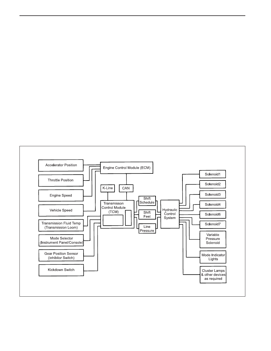
Output circuits which control external devices such
as the Variable Pressure Solenoid (VPS) driver, On/
Off solenoid drivers, a diagnostics output and the
driving mode indicator light.
Processing Logic
Shift schedule and calibration information is stored in
an Erasable Programmable Read Only Memory (EPROM).
Throttle input calibration constants and the diagnostics
information are stored in Electrically Erasable Program-
mable Read Only Memory (EEPROM) that retains the
memory even when power to the TCM is disconnected.
TCM continuously monitors the input values and uses
these, via the shift schedule, to determine the required
gear state. At the same time it monitors, via the solenoid
outputs, the current gear state, whenever the input
conditions change such that the required gear state is
different to the current gear state, the TCM initiates a
gear shift to bring the two states back into line.
Once the TCM has determined the type of gearshift
required the TCM accesses the shift logic, estimates
the engine torque output, adjusts the variable pressure
solenoid ramp pressure then executes the shift.
The TCM continuously monitors every input and output
circuit for short or open circuits and operating range.
When a failure or abnormal operation is detected the
TCM records the condition code in the diagnostics
memory and implements a Limp Home Mode (LHM).
The actual limp home mode used depends upon the
failure detected with the object to maintain maximum
drive-ability without damaging the transmission. In
general input failures are handled by providing a default
value. Output failures, which are capable of damaging
the transmission, result in full limp mode giving only
third or fourth gear and reverse. For further details of
limp modes and memory retention refer to the
Diagnostic Trouble Code Diagnosis Section.
T h e T C M i s d e s i g n e d t o o p e r a t e a t a m b i e n t
temperatures between - 40 and 85 °C (- 40 and 185 °F).
It is also protected against electrical noise and voltage
spikes, however all the usual precautions should be
observed, for example when arc welding or jump
starting.
TCM Inputs
To function correctly, the TCM requires engine speed,
vehicle speed, transmission fluid temperature, throttle
position, gear position and Kickdown Switch inputs to
determine the variable pressure solenoid current ramp
and on/off solenoid states.
KAA5A030
This ensures the correct gear selection and shift feel
for all driving conditions.
The inputs required by the TCM are as follows;
AUTOMATIC TRANSMISSION 5A-5
SSANGYONG MY2002
•
Engine Speed
The engine speed signal is derived from the Control-
ler Area Network (CAN) via Engine Control Module
(ECM).
•
Vehicle Speed
The vehicle speed sensor, which is located in the
transfer case, sends the output shaft speed signal
to the Engine Control Module (ECM). The information
is then transferred to the TCM via the CAN.
•
Transmission Fluid Temperature
The transmission fluid temperature sensor is a
thermistor located in the solenoid wiring loom within
the valve body of the transmission. This sensor is
a typical Negative Temperature Coefficient (NTC)
resistor with low temperatures producing a high
resistance and high temperatures producing a low
resistance.
If the transmission fluid temperature exceeds 135
°C (275 °F), the TCM will impose converter lock-up
at lower vehicle speeds and in some vehicles
flashes the mode indicator light. This results in
maximum oil flow through the external oil cooler and
eliminates slippage in the torque converter. Both
these actions combine to reduce the oil temperature
in the transmission.
Minimum
Temperature
(°C)
Resistance (Ohms)
-20
0
20
100
135 (Overheat
Mode Threshold)
13,638
5,177
2,278
117
75
Maximum
17,287
6,616
2, 723
196
85
Pin No.
Wire Color
Connects to
1
Red
Solenoid 1
2
Blue
Solenoid 2
3
Yellow
Solenoid 3
4
Orange
Solenoid 4
5
Green
Solenoid 5
6
Violet
Solenoid 6
7
Brown
Solenoid 7
8
Green
Solenoid 5
9
White
Temperature Sensor
10
Red
Temperature Sensor
Pin No. Codes and colors in Solenoid Loom
KAA5A040
KAA5A050
Gear Position Sensor
The gear position sensor is incorporated in the inhibitor
switch mounted on the side of the transmission case.
•
Inhibit starting of the vehicle when the shift lever is
in a position other than Park or Neutral
•
Illuminate the reverse lamps when Reverse is se-
lected
•
Indicate to the TCM which lever position has been
selected by way of a varying resistance.
The gear position sensor is a multi-function switch pro-
viding three functions;
KAA5A060
5A-6 AUTOMATIC TRANSMISSION
SSANGYONG MY2002
Solenoids
The TCM controls seven solenoids. Solenoids 1 to 6
(S1 to S6) are mounted in the valve body, while
Solenoid 7 (S7) is mounted in the pump cover.
•
Solenoid 1 and 2: S1 and S2 are normally open ON/
OFF solenoids that set the selected gear. These
solenoids determine static gear position by
operating the shift valves. Note that S1 and S2
solenoids also send signal pressure to allow or
prohibit rear band engagement.
•
Solenoid 3 and 4: S3 and S4 are normally open ON/
OFF solenoids that combine to control shift quality
and sequencing. S3 switches the clutch regulator
valve OFF or ON. S4 switches the front band regula-
tor valve OFF or ON. S5 also provides the signal
pressure for the converter clutch regulator valve.
•
Solenoid 5: S5 is a variable pressure solenoid that
ramps the pressure during gear changes. This sole-
noid provides the signal pressure to the clutch and
band regulator, thereby controlling the shift pres-
sures. S5 also provides the signal pressure for the
converter clutch regulator valve.
•
Solenoid 6: S6 is a normally open ON/OFF solenoid
that sets the high/low level of line pressure. Solenoid
OFF gives high pressure.
•
Solenoid 7: S7 is a normally open ON/OFF solenoid
that controls the application of the converter clutch.
Solenoid ON activates the clutch.
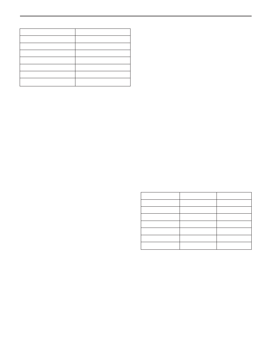
Solenoid Logic for Static Gear States
Gear
S1
S2
1st
ON
ON
2 n d
OFF
ON
3 r d
OFF
OFF
4th
ON
OFF
Reverse
OFF
OFF
Neutral
OFF
OFF
Park
OFF
OFF
Shift Lever Position
Resistance (k
Ω
Ω
Ω
Ω
Ω
)
Manual 1
1 ~ 1.4
Manual 2
21.8 ~ 2.2
Manual 3
3 3 ~ 3.4
Drive
4.5 ~ 4.9
Neutral
6.8 ~ 7.2
Reverse
10.8 ~ 11.2
Park
18.6 ~ 19
Kickdown Switch
The Kickdown Switch is used to signal the TCM that
the driver has pressed the acclerator to the floor and
requires a kickdown shift. When this switch is used,
the POWER light comes ON and the POWER shift
pattern is used.
Diagnostic Inputs
The diagnostic control input or K-line is used to initiate
the outputting of diagnostic data from the TCM to a
diagnostic test instrument. This input may also be used
to clear the stored fault history data from the TCM’s
retentive memory. Connection to the diagnostic input
of the TCM is via a connector included in the vehicle’s
wiring harness or computer interface.
Battery Voltage Monitoring Input
The battery voltage monitoring input is connected to
the positive side of the battery. This signal is taken
from the main supply to the TCM.
If the battery voltage at the TCM falls below 11.3 V,
the transmission will adopt a low voltage mode of
operating in which shifts into first gear are inhibited.
All other shifts are allowed but may not occur because
of the reduced voltage. This condition normally occurs
only when the battery is in poor condition.
If the battery voltage is greater than 16.5 V, the trans-
mission will adopt limp home mode and all solenoids
are turned OFF.
When system voltage recovers, the TCM will resume
normal operation after a 30 seconds delay period.
TCM Outputs
The outputs from the TCM are supplied to the compo-
nents described below;
•
Solenoids
•
Mode Indicator Light
Readings for Resistance / Shift Lever Positions

AUTOMATIC TRANSMISSION 5A-7
SSANGYONG MY2002
Shift
To Initiate Shift
Typical S5 Current Ramp
To Complete Shift
1-2
S1 OFF
750mA to 600mA
S4 OFF
S4 ON
1-3
S1 OFF
S3 OFF
S2 OFF
850mA to 750mA
S4 OFF
S3 ON
S4 ON
1-4
S2 OFF
S3 OFF
S3 ON
850mA to 750mA
S4 OFF
S4 ON
2-3
S2 OFF
700mA to 500mA
S3 OFF
S3 ON
S4 OFF
S4 ON
3-4
S1 ON
750mA to 600mA
S4 OFF
S4 ON
4-3
S4 ON
750mA to 900mA
S1 OFF
S4 OFF
4-2
S3 ON
S1 OFF
750mA to 950mA
S2 ON
S3 OFF
4-1
S3 ON
S2 ON
S4 ON
600mA to 1000mA
S3 OFF
S4 OFF
3-2
S2 ON
S4 OFF
S4 ON
600mA to 450mA @ 20 kph.
550mA to 400mA @ 60 kph.
800mA to 650mA @ 100 kph.
3-1
S3 ON
S1 ON
S4 ON
S2 ON
S3 OFF
700mA to 950mA
S4 OFF
2-1
S4 ON
800mA to 950mA
S1 ON
S4 OFF
Conv. Clutch
ON
S7 ON
700mA to 400mA
S7 OFF
OFF
600mA to 100mA
Solenoid Operation during Gearshifts
Нет комментариевНе стесняйтесь поделиться с нами вашим ценным мнением.
Текст