SsangYong Korando II (1996-2006 year). Manual — part 287

AUTOMATIC TRANSMISSION 5A-51
SSANGYONG MY2002
DIAGNOSTIC TROUBLE CODES (Cont'd)
DTC
P1745
P1746
P1747
Description
Solenoid 5 Circuit Short
Solenoid 6 Circuit Short
Solenoid 7 Circuit Short
5A-52 AUTOMATIC TRANSMISSION
SSANGYONG MY2002
Circuit Description
The Transmission Control Module (TCM) Diagnistic
System Check is the starting point for any driveability
complaint diagnosis. Before using this procedure,
perform a careful visual/physical check of the
T r a n s m i s s i o n C o n t r o l M o d u l e ( T C M ) a n d t h e
transmission grounds for cleanliness and tightness.
The TCM Diagnostic System Check is an organized
approach to identifying a problem created by an
electronic transmission control system malfunction.
TCM DIAGNOSTIC SYSTEM CHECK
Diagnostic Aids
An intermittent fault may be caused by a poor connec-
tion, rubbed-through wire insulation or a wire broken
inside the insulation. Check for poor connections or a
damaged harness. Inspect the TCM harness and con-
nections for improper mating, broken locks, improperly
formed or damaged terminals, poor terminal-to-wire
connection, and damaged harness.
TCM Diagnostic System Check
1
Step
Action
Value(s)
Yes
No
2
1 Turn the ignition OFF.
2. Install the scan tool.
3. Turn the ignition ON, with the engine OFF.
4. Attempt to display the Transmission Control
Module (TCM) Data List with the scan tool.
Does the scan tool display the TCM data?
Select the Trouble Code with the scan tool.
Are any Diagnostic Trouble Codes (DTCs) stored?
-
Go to Step 2
Go to Step 3
Go to
applicable
DTC table
-
System OK,
Check
Complete
KAA5A5KA

AUTOMATIC TRANSMISSION 5A-53
SSANGYONG MY2002
TCM Diagnostic System Check (Cont'd)
3
Step
Action
Value(s)
Yes
No
4
5
6
7
1. Turn the ignition OFF.
2. Disconnect the TCM connector B.
3. Turn the ignition ON.
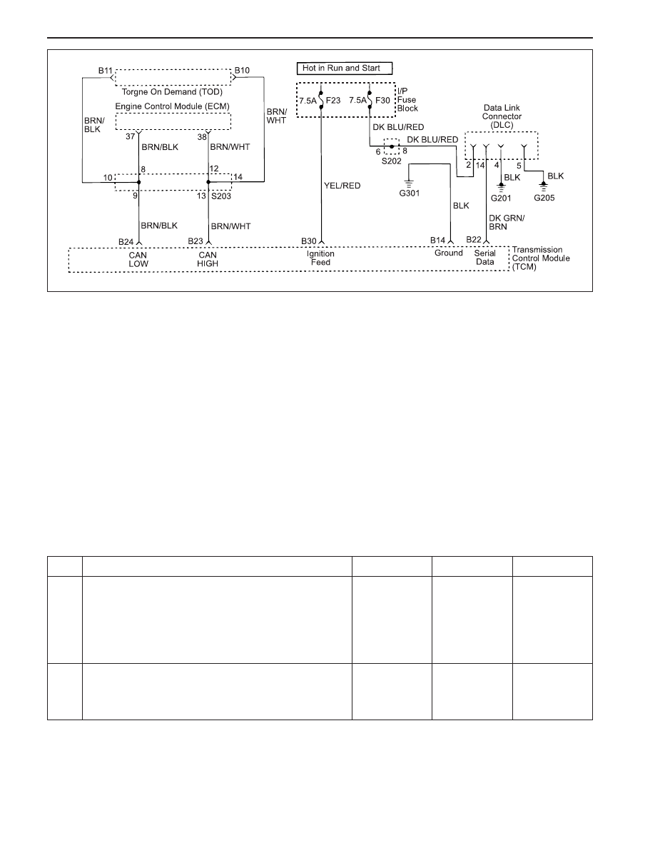
4. Check the serial data line from TCM connector
terminal B22 to Data Link Connector (DLC) connec-
tor terminal 14 for an open, short to ground, or
short to voltage. Also, check the DLC ignition feed
circuit for an open or short to ground and the DLC
ground circuit for an open.
Is a problem found?
Repair the open, short to ground or short to voltage in
the serial data circuit or the DLC ignition feed circuit
or the DLC ground circuit.
Is a repair complete?
Check the TCM ignition feed circuit for an open or
short to ground and the TCM ground circuit for an
open.
Is a problem found?
Repair the open or short to ground in the TCM ignition
feed circuit or the TCM ground circuit.
Is a repair complete?
1. Turn the ignition OFF.
2. Disconnect the TCM connector.
-
Go to Step 6
Go to Step 7
-
Go to Step 1
-
-
Go to Step 1
-
-
Go to Step 4
Go to Step 5
-
Go to Step 1
-
5A-54 AUTOMATIC TRANSMISSION
SSANGYONG MY2002
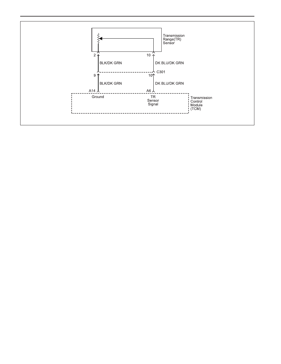
Circuit Description
The Transmission Range (TR) sensor is incorporated
in the inhibitor switch mounted on the side of the
transmission case. The TR sensor Indicates to the TCM
which gear position has been selected by way of a
varying resistance.
The TR sensor signal has discrete values indicating
the positions selected by the gear shift control lever
(PRND321). The Transmission Control Module (TCM)
receives that signal with a voltage varying from 0 V to
5 V. DTC P0706 sets when the TR sensor signal is not
feasi ble.
Conditions for Setting the DTC
•
The engine temperature is greater than 60 °C (140 °F).
•
The engine speed is greater than 2000 RPM and
less than 4000 RPM.
•
Engine load is greater than 60 %.
•
DTCs P0707, P0708, P1703 and P1719 are not set.
•
Transmission temperature is greater than 0 °C (32 °F)
o r i f P 0 7 1 0 i s p r e s e n t t h e e n g i n e c o o l a n t
temperature is greater than 60 °C (140 °F).
•
The TR sensor indicates that the transmission is in
a neutral state, however the engine output torque
indicates that a drive gear load is present. This
condition must be continuously present for 5
seconds.
DIAGNOSTIC TROUBLE CODE (DTC) P0706
TRANSMISSION RANGE SENSOR CIRCUIT RANGE/PERFORMANCE
Action Taken When the DTC Sets
•
The Malfunction Indicator Lamp (MIL) will illuminate
on the second consecutive driving cycle with the
DTC present.
•
The EOBD system will record operating conditions
at the time the diagnostic fails. This information will
be stored in the Failure Records buffer.
•
TR signal is assumed to be in the Drive position.
•
The transmission is limited to 2nd and R gears only.
Namely 1st, 3rd and 4th gears are inhibited.
•
Torque Converter Clutch (TCC) is disabled.
Conditions for Clearing the DTC
•
The DTC will clear when the malfunction has not oc-
curred for 30 seconds and TR is in P, R, N or D.
•
A history DTC will clear after 40 TCM power-up
cycles with a warm transmission (>50 °C) and
without a fault.
•
History DTCs can be cleared by using a scan tool.
Diagnostic Aids
•
Inspect the wiring for poor electrical connections
at the TCM and at the TR sensor connector. Look
for possible bent, backed out, deformed or damaged
ter-minals. Check for weak terminal tension as well.
Also, check for chafed wires that could short to bare
metal or other wiring. Inspect for broken wires inside
the in-sulation.
KAA5A5LA
Нет комментариевНе стесняйтесь поделиться с нами вашим ценным мнением.
Текст