SsangYong Korando II (1996-2006 year). Manual — part 398

SUPPLEMENTAL RESTRAINTS SYSTEM 8B-5
SSANGYONG MY2002
KAA8B060
AIRBAG WARNING LAMP
The instrument cluster contains an airbag warning indi-
cator bulb to verify the operation of the airbag indicator
and sensing and diagnostic module (SDM). The SDM
performs a start-up test when the ignition is turned ON
and turns the airbag indicator on for 4.5 seconds by
supplying an internal ground to the indicator lamp
circuit. After 4.5 seconds, the airbag indicator will turn
off if no more malfunctions have been detected.
If the SDM has detected malfunctions, which could
potentially affect the operation of the supplemental
restraint system (SRS) it turns on or blinks the airbag
warning indicator. The airbag indicator stays on for
the malfunction of internal system and blinks for
external circuit problem such as short to battery or
ground. The airbag indicator blinks four different modes
according to the fault.
Some malfunctions could result in non-deployment
when necessary or deployment under conditions which
would no normally result in deployment.
When the SDM is not properly attached to its connector
the airbag circuit is shorted to ground because there
is a shorting bar within the SDM electronic connector.
The shorting bar is disengaged when proper connection
is made, but if a poor connection exists the SDM
connector supplies a ground to the airbag indicator in
dependently of the SDM, and the airbag indicator turns
on.
CLOCK SPRING
Caution: Disassembling the clock spring can cause
injury or cause the clock spring to malfunction.
Caution: Over-rotating the clock spring without the
steering wheel in position could damage the clock
spring and result in an inoperative driver airbag.
There is a coil assembly in the steering which is referred
to as a clock spring because of its internal resemblance
to the type of spring used in a mechanical clock. The
clock spring should never be disassembled, and there
is no timekeeping function. The clock spring contains
current- carrying coils. One of the current-carrying coils
maintains continuous contact within the driver deploy-
ment loop while the steering wheel is rotated. The clock
spring also contains coils that maintain continuous con-
tact for horn and remote audio control switch.
Turning the steering wheel in one direction tightens
the coil, and turning the steering wheel in the opposite
direction loosens the coil. Do not turn the clock spring
when the steering wheel is not attached.
A yellow two-way connector on the lower steering col-
umn is attached to the clock spring wiring.
WIRING HARNESS CONNECTORS
If the sensing and diagnostic module (SDM) electrical
connector is not attached properly, a built in shorting
bar will connect the wire from airbag warning lamp with
the SDM ground wire. This turns on the airbag indicator.
To prevent deployment during servicing, additional
shorting bars are located in following locations:
•
The clock spring electrical connector at the lower
steering column.
•
The passenger airbag module.
•
The driver airbag module.
•
The seat belt pretensioners.
•
The SDM connector.
The shorting bar is only a backup safety device. Always
disable the supplemental restraints system (SRS) be-
fore beginning any service procedure.
KAA8B070

SSANGYONG MY2002
8B-6 SUPPLEMENTAL RESTRAINTS SYSTEM
COMPONENTS LOCATOR
SRS COMPONENT AND WIRING LOCATION VIEW
1 Driver Airbag Module & Clock Spring
2 Passenger Airbag Module
3 Sensing And Diagnostic Module (SDM)
KAA8B080
4 Data Link Connector (DLC)
5 Pretensioner (at A Pillar)
SUPPLEMENTAL RESTRAINTS SYSTEM 8B-7
SSANGYONG MY2002
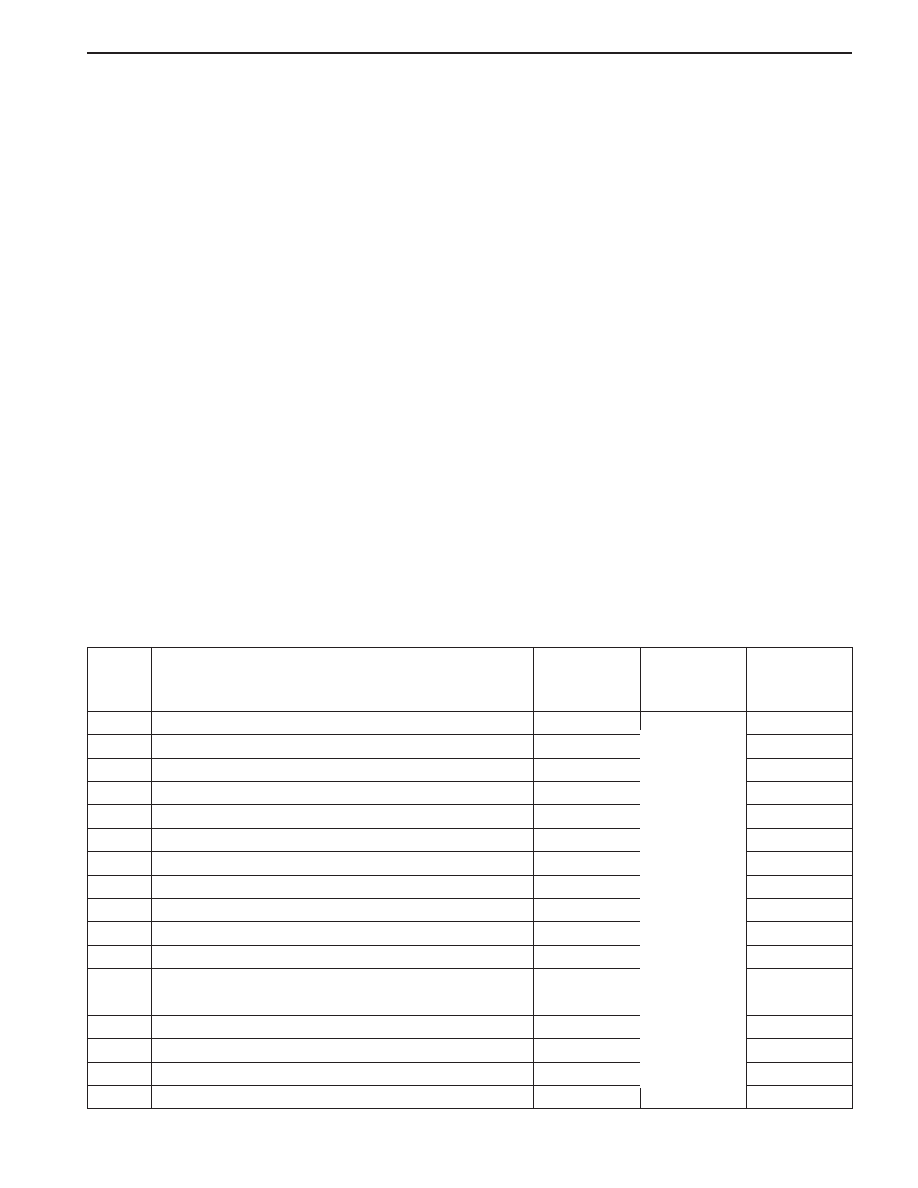
Driver Deployment Loop Shorted to Voltage
Passenger Deployment Loop Shorted to Voltage
Driver Seat Belt Pretensioner Shorted to Voltage
Passenger Seat Belt Pretensioner Shorted to Voltage
Driver Deployment Loop Shorted to Ground
Passenger Deployment Loop Shorted to Ground
Driver Seat Belt Pretensioner Shorted to Ground
Passenger Seat Belt Pretensioner Shorted to Ground
Driver Energy Shutdown Switch Error
Passenger Energy Shutdown Switch Error
Driver Seat Belt Pretensioner Energy Shutdown Switch Error
Passenger Seat Belt Pretensioner Energy Shutdown
Switch Error
Driver Ignition Switch Fault Internal
Passenger Ignition Switch Fault Internal
Driver Seat Belt Pretensioner Ignition Switch Fault
Passenger Seat Belt Pretensioner Ignition Switch Fault
01
02
03
04
05
06
07
08
09
10
11
12
13
14
15
16
DIAGNOSTIC INFORMATION AND PROCEDURES
DIAGNOSTIC TROUBLE CODES
(DTC)
When the sensing and diagnosticmodule (SDM)
detects any problem it illuminates or blinks the airbag
warning indicator and keeps the diagnostic trouble
codes (DTCs). The supplemental restraint system
(SRS) Diagnostic System Check must always be the
starting point for any SRS diagnosis. The SRS
Diagnostic System Check reveals DTCs through the
use of scan tool. It also checks for proper airbag
warning lamp operation.
The two types of DTCs that may be recorded are as
follows:
1. Current DTCs represent malfunction currently being
detected. Current DTCs are stored in random
access memory (RAM).
2. Historic DTCs represent malfunctions detected since
the last time the historic memory was cleared.
Historic DTCs are stored in the electrically erasable
programmable read-only memory (EEPROM).
The DTC is differentiates internal and external faults
upon the cause of the defects. Internal faults can not
be cured, replace the SDM. Refer to “Diagnostic
Trouble Code Table” in this section.
SCAN TOOL DIAGNOSTICS
A scan tool can read serial data from terminal 9 of the
data link connector (DLC). The scan tool is used to
read diagnostic trouble codes (DTCs), and to clear
some DTCs after a repair is completed. By design,
certain codes cannot be cleared.
To use the scan tool, turn the ignition OFF, connect
the scan tool to the DLC, and turn the ignition switch
to ON. Follow the instructions in the scan tool manual.
The SDM sends serial data from terminal 20 of the
SDM to terminal 9 of the DLC.
USE OF SPECIAL TOOLS
Use a scan tool to read and clear diagnostic trouble
codes (DTCs). A connector adapter kit provides
jumper wires and terminal adapters to make it easier
to test small terminals. In diagnostic testing, use load
tool or dummy resistance to substitute for airbag
modules.
DIAGNOSTIC TROUBLE CODE TABLE
DTC
Description
Airbag Warn-
ing Indicator
Blink Mode
Error Handing
Type of the
Faults
Internal
Internal
Internal
Internal
Internal
Internal
Internal
Internal
3
3
4
4
3
3
4
4
Partial
Shutdown

SSANGYONG MY2002
8B-8 SUPPLEMENTAL RESTRAINTS SYSTEM
Driver Deployment Loop Resistance High
Passenger Deployment Loop Resistance High
Driver Seat Belt Pretensioner Deployment Loop
Resistance High
Passenger Seat Belt Pretensioner Deployment Loop
Resistance High
Driver Deployment Loop Resistance Low
Passenger Deployment Loop Resistance Low
Driver Seat Belt Pretensioner Deployment Loop
Resistance Low
Passenger Seat Belt Pretensioner Deployment Loop
Resistance Low
Driver Deployment Loop Energy Reserve Voltage
Passenger Deployment Loop Energy Reserve Voltage
Driver Seat Belt Pretensioner Deployment Loop Energy
Reserve Voltage
Passenger Seat Belt Pretensioner Deployment Loop
Energy Reserve Voltage
System Energy Reserve Voltage
Safety Energy Reserve Capacitor Voltage
Driver Deployment Loop Energy Reserve Current off
Capacity
Passenger Deployment Loop Energy Reserve Current
off Capacity
Driver Seat Belt Pretensioner Deployment Loop Energy
Reserve Current off Capacity
Passenger Seat Belt Pretensioner Deployment Loop
Energy Reserve Current off Capacity
5th Energy Reserve Current off Capacity
Condenser Voltage
Collision Times Checksum
Accelerometer Error
Accelerometer Off-Set Error
Arming Sensor Shorted
Major Upper Side Application Specific Integrated Circuit
Application Specific Integrated Circuit Over Heat
Micro Control Unit Error
Standard Band Gap
Temperature Sensor
Warning Lamp circuit open or short to ground/battery
17
18
19
20
21
22
23
24
25
26
27
28
29
30
31
32
33
34
35
36
37
38
39
40
41
42
43
44
45
46
Diagnostic Trouble Code Table (Cont’d)
DTC
Description
Airbag Warn-
ing Indicator
Blink Mode
Error Handing
Type of the
Faults
Internal
Internal
Internal
Internal
Internal
Internal
Internal
Internal
Internal
Internal
Internal
Internal
Internal
Internal
Internal
Internal
Internal
Internal
Internal
Internal
Internal
1
2
4
4
1
2
4
4
Partial
Shutdown
Total
Shutdown
Нет комментариевНе стесняйтесь поделиться с нами вашим ценным мнением.
Текст