SsangYong Korando II (1996-2006 year). Manual — part 370
SSANGYONG MY2002
6C-10 POWER STEERING GEAR
KAA6C090
KAA6C100
KAA6C110
KAA6C080
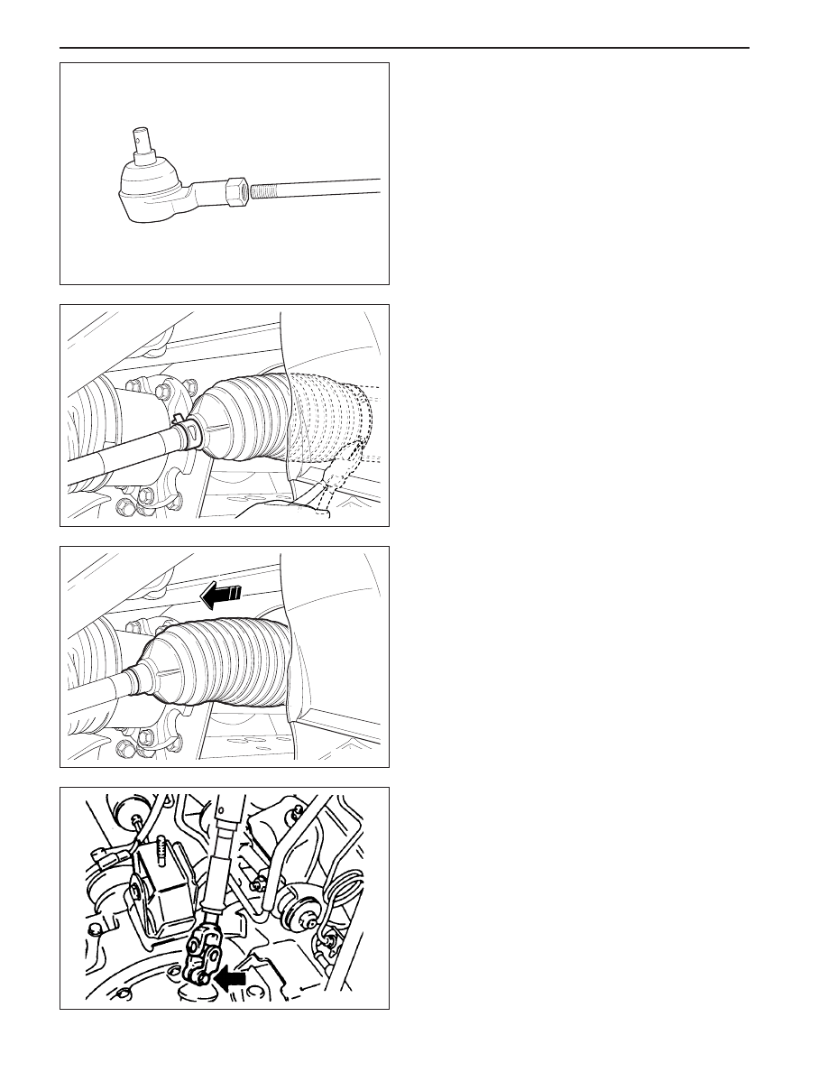
4. Loosen the outer tie rod adjusting nut and remove
the outer tie rod by twisting it off the inner tie rod.
Installation Notice:
•
After Installation, perform a front toe adjustment.
Refer to Section 2B, Wheel Alignment.
DUST BOOT
Removal and Installation Procedure
1. Raise and suitably support the vehicle.
2. Remove the wheel. Refer to Section 2E, Tires and
wheels.
3. Remove the outer tie rod. Refer to “Outer Tie Rod”
in this section.
4. Remove the dust boot retaining clamps.
5. Remove the dust boot.
Installation Notice:
•
After Installation, perform a front toe adjustment.
Refer to Section 2B, Wheel Alignment.
INTERMEDIATE SHAFT
Removal and Installation Procedure
1. Turn the steering wheel until it is horizontal. This
is the straight-ahead position. Make a mark on
the stub shaft housing that lines up with a mark
on the intermediate shaft lower universal joint.
Installation Notice:
•
When attaching the lower universal joint, the
marks on the intermediate shaft and on the stub
shaft should line up
POWER STEERING GEAR 6C-11
SSANGYONG MY2002
KAA6C120
KAA6C130
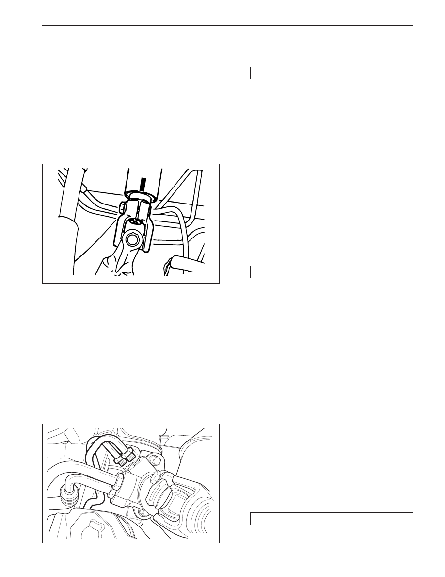
2. Remove the lower pinch bolt from the universal
joint on the intermediate shaft.
Installation Notice
Tightening Torque
27 N•m (20 lb-ft)
3. Make a mark on the steering column shaft that
lines up with a mark on the intermediate shaft
upper universal joint.
Installation Notice:
•
When attaching the upper universal joint, the
marks on the intermediate shaft and steering
column shaft should line up
4. Remove the upper pinch bolt from the universal
joint on the intermediate shaft.
Installation Notice
5. Remove the intermediate shaft.
Tightening Torque
27 N•m (20 lb-ft)
HYDRAULIC CYLINDER LINES
Removal and Installation Procedure
1. Siphon the power steering fluid from the power
steering fluid reservoir.
2. Disconnect the power steering gear hydraulic
cylinder pipes from the power steering gear at the
valve end. Replace the O-ring seals as needed.
Installation Notice
Tightening Torque
14 N•m (10 lb-ft)

SSANGYONG MY2002
6C-12 POWER STEERING GEAR
KAA6C140
3. Raise and suitably support the vehicle.
4. Disconnect the power steering gear hydraulic
cylinder pipes from the power steering gear at the
cylinder end.
5. Remove the steering gear hydraulic cylinder pipes
from the vehicle.
Installation Notice
Tightening Torque
61 N•m (44 lb-ft)
•
When adding power steering fluid or making a
complete change, always use DEXRON. - II pow-
er steering fluid. Failure to use the proper fluid
will cause hose and seal damage and fluid
leaks.
•
Fill the reservoir with power steering fluid.
•
Inspect for leaks. If there are leaks, correct the
cause of the leaks and bleed the system. Refer
to “Bleeding the Power Steering System” in this
section.

POWER STEERING GEAR 6C-13
SSANGYONG MY2002
KAA6C150
UNIT REPAIR
RACK AND PINION
Disassembly and Assembly Procedure
1. Remove the rack and pinion assembly from the
vehicle. Refer to “Rack and Pinion Assembly” in
this section.
2. Remove the valve and pinion assembly from the
rack and pinion steering assembly. Refer to “Valve
and Pinion” in this section.
3. Remove the rack bearing assembly from the rack
and pinion steering assembly. Refer to “Rack
Bearing” in this section.
4. Mark the threads on the inner tie rod to aid in
repositioning the adjusting nut.
5. Loosen the adjusting nut and remove the outer tie
rod nut and the adjusting nut.
Installation Notice:
•
When installing the outer tie rod nut, the mark
on the inner tie rod and adjusting nut should
line up.
•
After installation, perform a front toe adjustment.
Refer to Section 2B, Wheel Alignment.
KAA6C160
KAA6C170
6. Remove the dust boot retaining clamps and
remove the dust boot.
7. Push back the retainer holding the connection be-
tween the inner tie rod and the power steering gear
rack.
Нет комментариевНе стесняйтесь поделиться с нами вашим ценным мнением.
Текст