SsangYong Korando II (1996-2006 year). Manual — part 324

AUTOMATIC TRANSMISSION 5A-199
SSANGYONG MY2002
1. Measure the projection of the front servo push rod
from the transmission case dimension ‘A’.
a. Apply air at 650/700 kPa to the front servo apply
area (B1 outer)
b. Measure the travel of the push rod and subtract
3 mm to find the shim size required.
c. Release the air.
Notice: A minimum of one shim is required at all times
- minimum shim size is 1 mm. The thickness of
available shims are listed in the table below.
FRONT AND REAR BAND ADJUSTMENT
Front Band Setting Procedure
2. Fit the selected shim(s) to the shank of the anchor
strut as follows:
a. Inspect the shim(s) for damage, wear or corro-
sion. Replace as necessary.
b. The shim(s) are to be installed between the case
abutment face and the anchor strut flange.
c. The shim(s) are to be fitted by hand and under
no circumstances to be hammered or forced.
d. Shim(s) are to be pressed on by hand until an
audible click is heard. The click indicates that
the shim is clipped home correctly.
3. Re-check that the push rod travel. (3 mm ± 0.25
mm)
KAA5A2E0
Thickness (mm)
Part Number
0.95/1.05
0574-037017
1.15/1.25
0574-037018
1.44/1.56
0574-037019
1.73/1.87
0574-037020
1.93/2.07
0574-037021
2.12/2.28
0574-037022
2.42/2.58
0574-037023
2.61/2.79
0574-037024
5A-200 AUTOMATIC TRANSMISSION
SSANGYONG MY2002
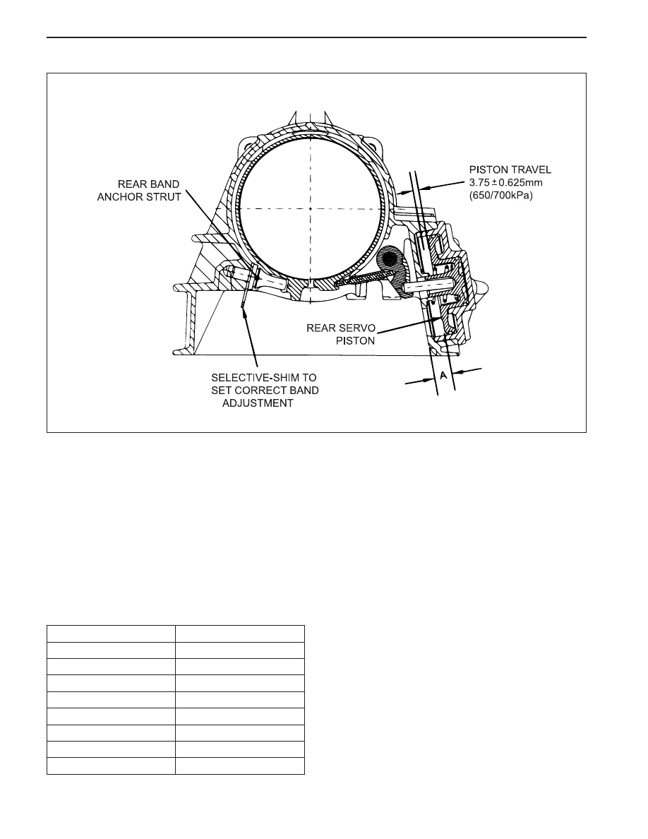
1. Measure distance‘A’ from the rear servo piston to
the inner face of the transmission case using vernier
calipers.
a. Apply air at 650/700 kPa to the rear servo apply
area (B2 outer)
b. Measure the travel of the piston, subtract 3.75
mm and divide the remainder by 2.5 to find shim
size.
c. Release the air.
Notice: A minimum of one shim is required at all times
- minimum shim size is 1 mm. The thickness of
available shims are listed in the table below.
Rear Band Setting Procedure
2. Fit the selected shim(s) to the shank of the anchor
strut as follows.
a. Inspect the shim(s) for damage, wear or
corrosion and replace as necessary. The shim(s)
are to be installed between the case abutment
face and the anchor strut flange.
b. The shim(s) are to be fitted by hand and under
no circumstances to be hammered or forced
c. The shim(s) are to be pressed on by hand until
an audible click is heard. The click indicates
that the shim is clipped home correctly.
3. Re-check that the piston travel.
(3.75 mm ± 0.625 mm)
KAA5A2F0
Thickness (mm)
Part Number
0.0.95/1.05
0574-037017
1.15/1.25
0574-037018
1.44/1.56
0574-037019
1.73/1.87
0574-037020
1.93/2.07
0574-037021
2.12/2.28
0574-037022
2.42/2.58
0574-037023
2.61/2.79
0574-037024

AUTOMATIC TRANSMISSION 5A-201
SSANGYONG MY2002
KAA5A2G0

5A-202 AUTOMATIC TRANSMISSION
SSANGYONG MY2002
KICKDOWN SWITCH
1. Separate the Kickdown Switch from the Kickdown
Switch bracket by pushing the lock.
2. Disconnect the Kickdown Switch connector.
3. Installation should follow the removal procedure in
the reverse order.
KAA5A5S0
GEAR SHIFT CONTROL LEVER
Disassembly and Assembly Procedure
1. Disconnect the negative battery cable.
2. Remove the gear shift control lever assembly.
Refer to Section 9G, interior Trim.
3. Remove the gear shift control lever knob.
4. Separate the upper and middle housing from the
gear shift control lever assembly by unlocking the
lock.
5. Remove the upper housing.
6. Disconnect the P position lamp by turning it from
the middle housing.
7. Remove the P position switches assembly bolts.
8. Remove the middle housing with the mode
selector switch wiring harness from the gear shift
control lever assembly.
9. Separate the P position switches assembly with
the P position lamp wiring harness from the gear
shift control lever assembly.
Notice: Adjust the brake transmission shift interlock
ease the operation well.
10. Remove the clips supporting the springs and
bushes from the pin of the pin of the gear shift
control lever.
11. Remover the spring and bushes from the pin of
the gear shift control lever.
12. Remove the gear shift control lever by pushing
the pin.
13. Installation should follow the removal procedure
in the reverse order.
KAA5A5P0
KAA5A5Q0
KAA5A5R0
Нет комментариевНе стесняйтесь поделиться с нами вашим ценным мнением.
Текст