SsangYong Korando II (1996-2006 year). Manual — part 348
SSANGYONG MY2002
5D1-68 TRANSFER CASE
KAA5D280
KAA5D290
KAA5D300
KAA5D310
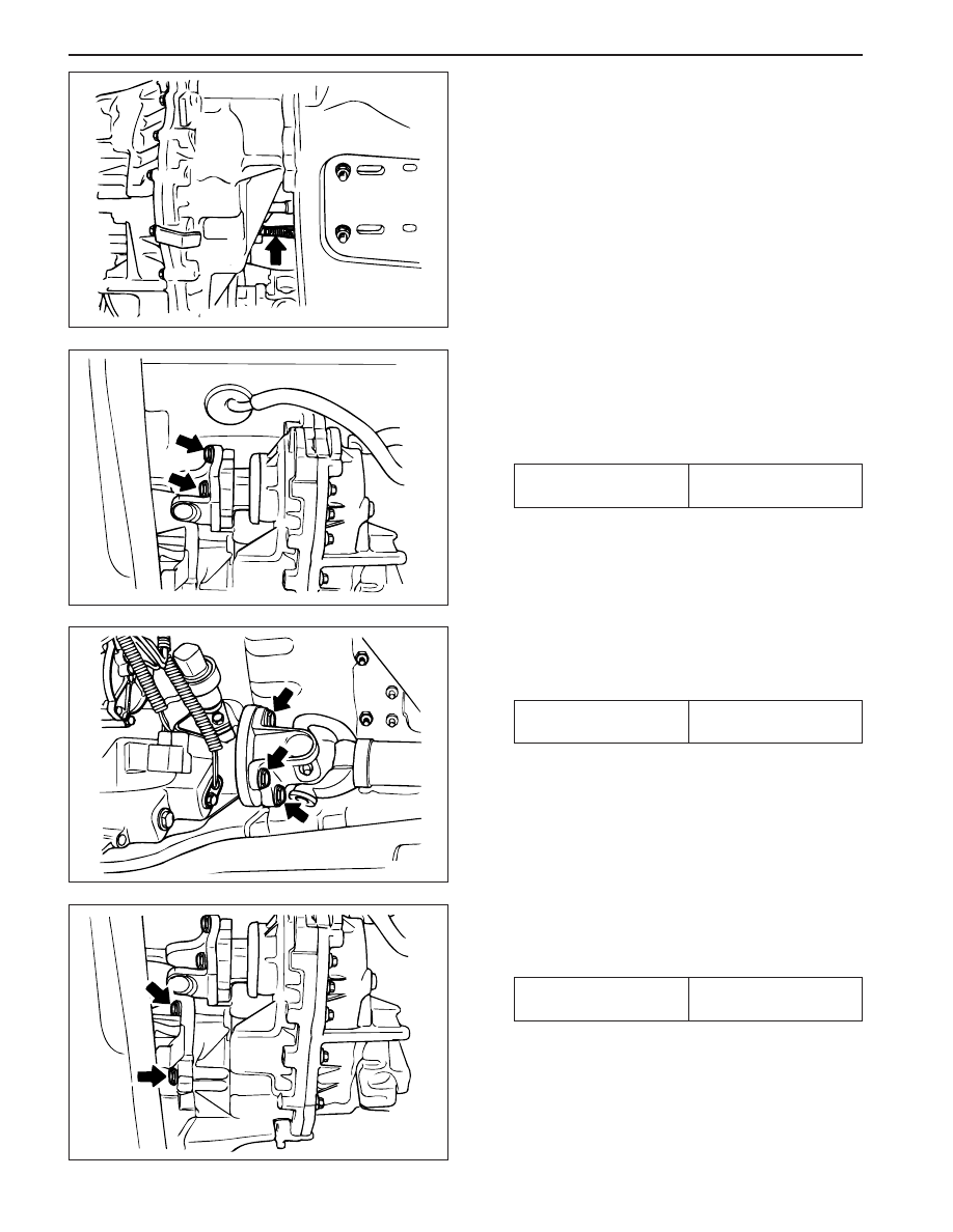
8. Disconnect breather hose on the front upper side
of the transfer case near front propeller shaft.
12. Remove five bolts that connect transfer case and
transmission adapter housing.
Installation Notice
11. Remove 4 bolts that connecting the rear propeller
shaft and rear output shaft flange.
Installation Notice
9. Prepare a hydraulic jack and support the transfer
case assembly.
10. Remove 4 bolts that connecting the front propeller
shaft and front output shaft/flange.
Installation Notice
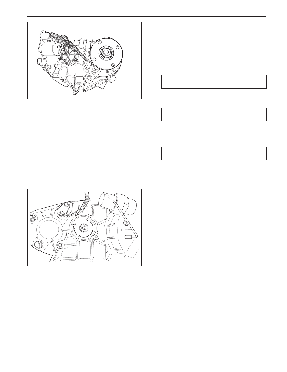
•
Make sure the connecting surface is clean.
•
Apply long life grease inside transfer case input
shaft.
13. Installation should follow the removal procedure
in the reverse order.
Tightening Torque
81 - 89 N•m
(60 - 66 lb-ft)
Tightening Torque
81 - 89 N•m
(60 - 66 lb-ft)
Tightening Torque
38 - 52 N•m
(28 - 38 lb-ft)
TRANSFER CASE 5D1-69
SSANGYONG MY2002
KAA5D320
KAA5D330
SHIFT MOTOR
Removal and Installation Procedure
1. Disconnect the negative battery cable.
2. Disconnect shift motor and clutch coil connector
(black 7 pin) on upper backside of transfer case.
3. Remove three shift motor mounting bolts.
Installation Notice
6. Keeps the shift motor even and pull out carefully.
Notice: When removing shift motor, pay attention
to the location of triangular slot and shaft in
transfer case inside motor and mark the position.
7. Installation should follow the removal procedure
in the reverse order.
Installation Notice:
•
Clean the connection surface between transfer
case and shift motor.
•
Apply black non-acid cure silicone rubber or
equivalent to the surface.
•
Do not disassemble the shift motor and replace
with new one, if necessary.
•
Make sure the motor position to match with 4H/
4L switch selection.
4. Remove one shift motor bracket bolt.
Installation Notice
5. Loose two adjusting bolts on the shift motor if
neces-sary.
Installation Notice
Tightening Torque
8 - 11 N•m
(70 - 97 lb-in)
Tightening Torque
8 - 11 N•m
(70 - 97 lb-in)
Tightening Torque
3 - 5 N•m
(27 - 44 lb-in)
SSANGYONG MY2002
5D1-70 TRANSFER CASE
KAA5D340
KAA5D350
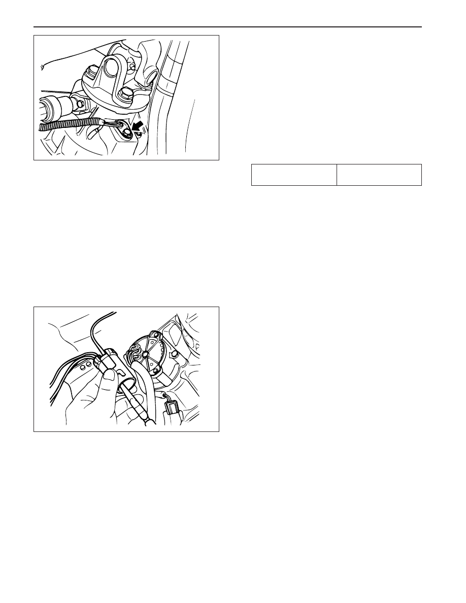
FRONT AND REAR PROPELLER
SHAFT SPEED SENSOR
Removal and Installation Procedure
1. Disconnect negative battery cable.
2. Disconnect front and rear speed sensor connector
(white 7 pin).
3. Remove shift motor. Refer to “Shift Motor” in this
sec-tion.
4. Remove front and rear propeller shaft speed
sensor retaining bolts.
Installation Notice
6. Disassemble the connector of front and rear
propeller shaft speed sensor.
7. Replace front or rear propeller shaft speed sensor,
as necessary.
Notice:
•
While replacing the speed sensor, make sure
the proper pin position.
•
Do not remove one wire to clutch coil in the
transfer case.
•
Make tidy on the wiring harness including
conduct tube.
8. Installation should follow the removal procedure
in the reverse order.
5. Remove the speed sensors by lifting up using
a tool such as flat screw drive.
Notice: Do not shock the speed sensor because
it is too sensitive at shock.
Tightening Torque
3 - 6 N•m
(27 - 53 lb-in)
TRANSFER CASE 5D1-71
SSANGYONG MY2002
KAA5D360
KAA5D330
KAA5D380
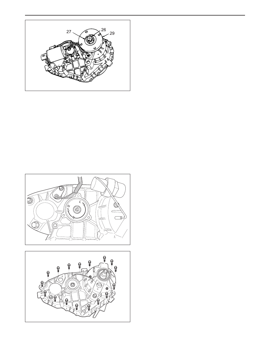
UNIT REPAIR
TRANSFER CASE OVERHAUL
Disassembly Procedure
1. Remove the transfer case assembly. Refer to
“Transfer Case” in this section.
2. Disassemble the white 7 pin connector of propeller
s h a f t s p e e d s e n s o r a n d s e p a r a t e t h e p i n
connected to brown wire to clutch coil.
3. Remove the propeller shaft speed sensors with
wires. Refer to “Front and Rear Propeller Shaft
Speed Sensor” in this section.
4. Remove vehicle speed sensor. Refer to Section
1F, Engine Control.
7. Remove the bolts that retain the front case to the
rear cover.
Notice:
•
Make sure that the front case is facing
downward so that the rear cover is facing
upwards.
•
Pry on the bosses and separate the front case
from the rear cover.
•
Remove all traces of gasket sealant from the
mating surfaces of the front case and rear cover.
5. Remove shift motor/clutch coil. Refer to “Shift
Motor and Clutch Coil” in this section.
Notice: When removing shift motor, pay attention
to the location of triangular slot and shaft in
transfer case inside motor and mark the position.
6. Using a 30 mm thin-wall socket, first remove the
rear output shaft nut, rear output shaft yoke
washer, oil seal then the rear output shaft flange.
Нет комментариевНе стесняйтесь поделиться с нами вашим ценным мнением.
Текст