SsangYong Musso. Manual — part 443

HYDRAULIC BRAKES 4A-11
Adjustment Procedure
1. Pedal Height
Notice
If pedal height is not in specified value, loosen the stop
lamp nut (B) and adjust the pedal height.
2. Pedal Stroke
Height (A)
150 mm (From the carpet)
Notice
If pedal stroke is not in specified value, loosen the stop bolt
and lock nut (F) and adjust the pedal stroke.
3. Free Play
Stroke (C)
Mando : 138 mm
PBR : 132mm
Notice
To adjust, depress the brake pedal several times until there
is no more vacuum left in the vacuum line.
To adjust, loosen the lock nut (D) of the push rod and turn
the rod.
Free Play (E)
1 - 4 mm
Inspection Procedure
1. Inspect the wear of bushing.
2. Inspect the warp and bend of brake pedal.
3. Inspect the return spring of brake pedal.
4. Inspect the conductivity when connecting the tester to the
stop lamp switch connector.
4A-12 HYDRAULIC BRAKES
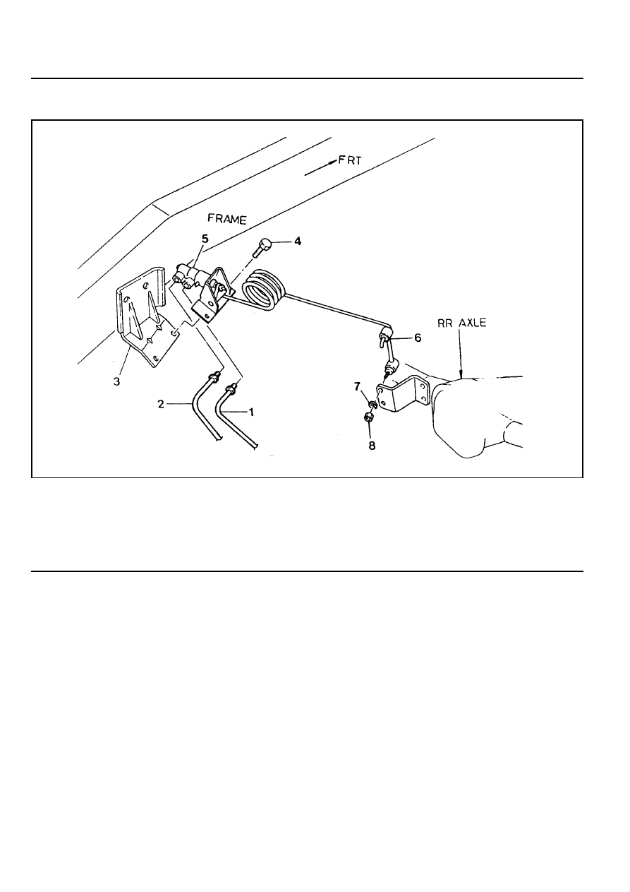
LCRV (LOAD CONSCIOUS REDUCING VALVE)
1 Brake Tube (from the master cylinder)
2 Brake Tube (from the rear brake)
3 LCRV Bracket
4 Bolt . . . . . . . . . . . . . . ... 12 Nm
5 LCRV Assembly
6 Connecting Link
7 Spring Washer
8 Nut . . . . . . . . . . . . . ... 14-18 Nm
HYDRAULIC BRAKES 4A-13
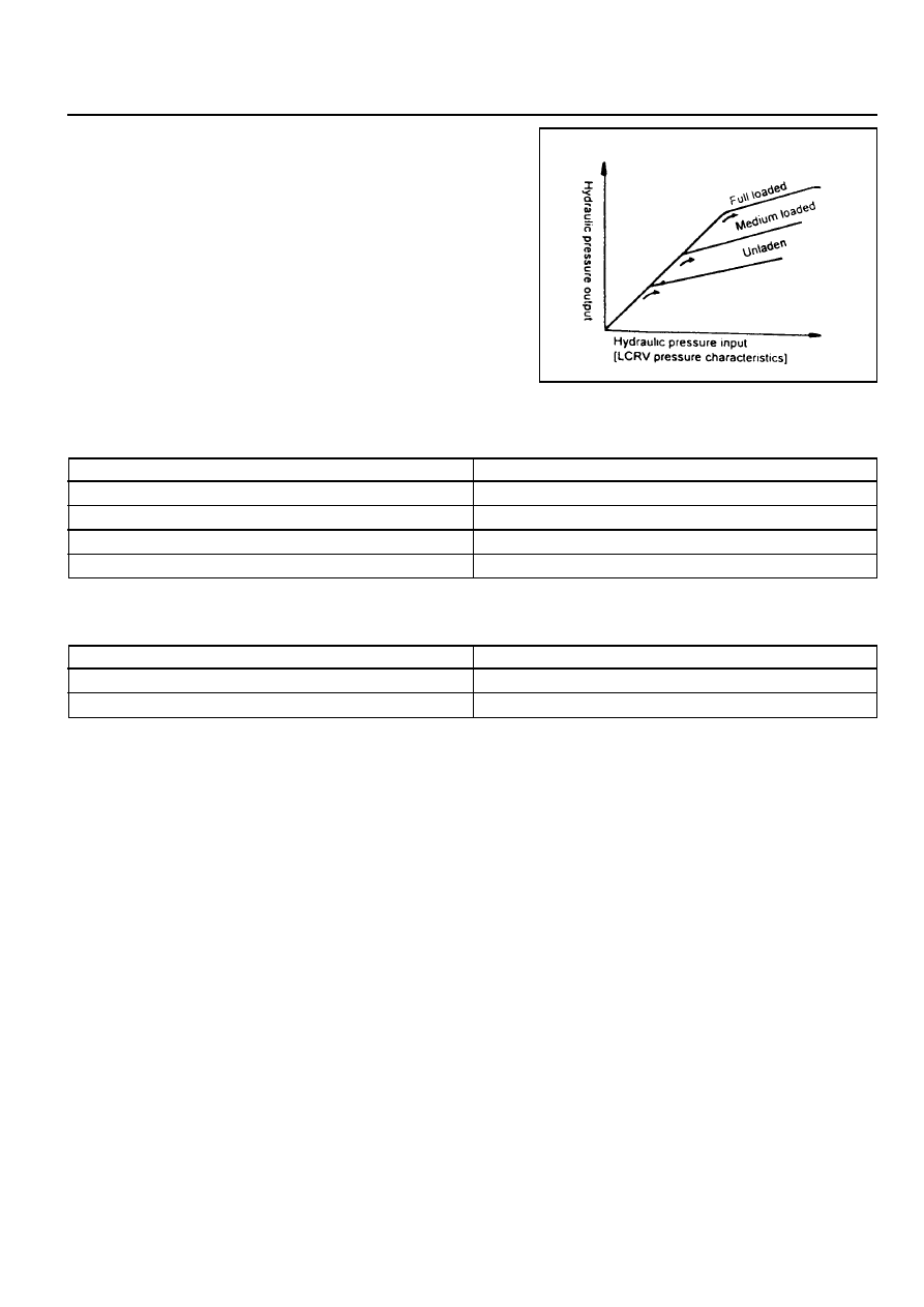
Construction
LCRV consists of sensing part and hydraulic control part.
1. Sensing Part
It detects the changes of vehicle height caused by vehicle
load. It consists of load sensing spring and control lever
which change according to vehicle load.
2. Hydraulic Control Part
It consists of valve stem devices which controls hydraulic
pressure according to load detected by sensing part.
Trouble Shooting
Poor Braking
Possible Cause
Air in Brake System
Poor Adjustment of Sensor Spring
Damaged Sensor Spring
Fluid Leaking from LCRV
Remedy
Bleeding
Adjust
Replace
Replace
Possible Cause
Poor Adjustment of Sensor Spring
Internal Fluid Leaking of LCRV
Remedy
Adjust
Replace
Abnormal Locking
4A-14 HYDRAULIC BRAKES
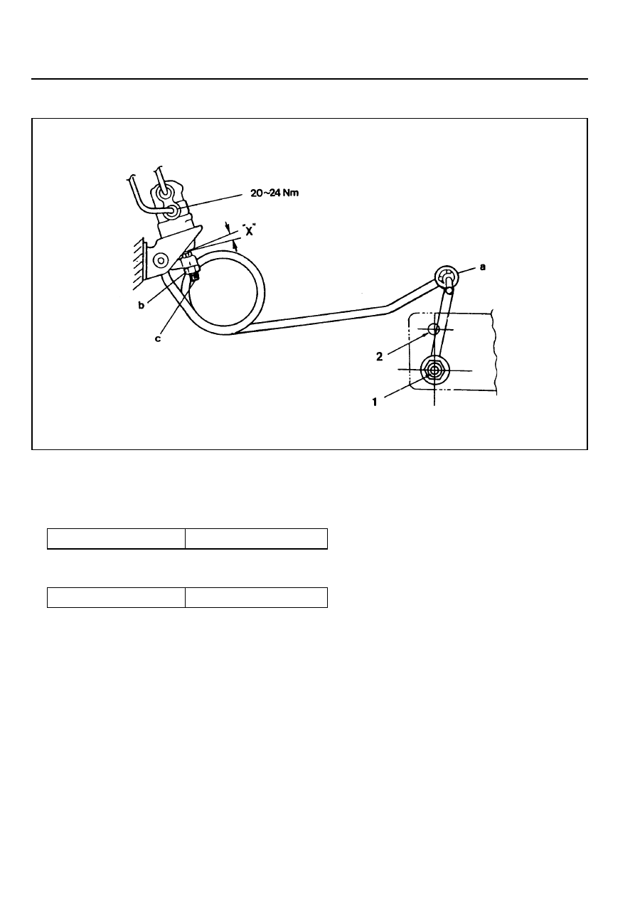
LCRV SETTING METHOD
1. LCRV setting should be performed with unladen vehicle
condition.
2. Install the connecting rod (a) to the No.1 hole.
Tightening Torque
14 - 18 Nm
3. Adjust the clearance “X” to be 0 mm and tighten the bolt (c)
using the lock nut (b).
Tightening Torque
14 - 18 Nm
4. Remove the connecting rod (a) from the No.1 hole and
reinstall it to the No. 2 hole.
5. Place alignment marks between the lock nut (b) and
adjusting screw (c) after the valve setting.
Нет комментариевНе стесняйтесь поделиться с нами вашим ценным мнением.
Текст