SsangYong Musso. Manual — part 226
FRONT SUSPENSION 2C-5
Removal & Installation Procedure
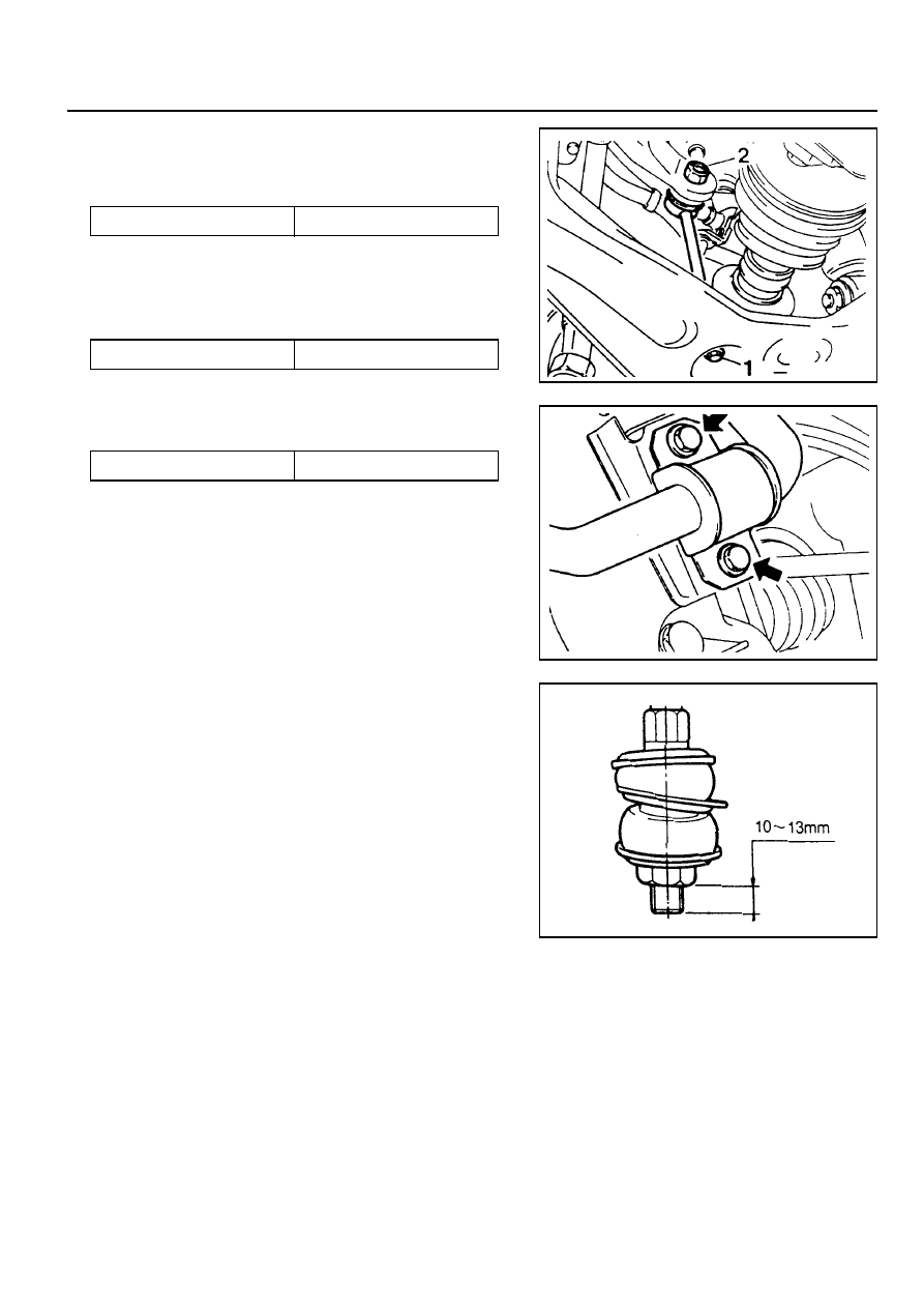
1. Remove the connecting nuts (1) from stabilizer bar link.
Installation Notice
2. Remove the connecting nuts (2) of the stabilizer bar and
link and then remove the link.
Installation Notice
3. Remove the stabilizer bar fixing cap bolts (arrow) and
remove the stabilizer bar.
Tightening Torque
60 - 80 Nm
4. Installation should follow the removal precedure in the
reverse order.
Notice
The distance between the end of the nut and the end of the
link should be in 10-13 mm at the connection of the stabilizer
bar link and lower arm.
Tightening Torque
30 - 45 Nm
Tightening Torque
16 - 22 Nm
2C-6 FRONT SUSPENSION
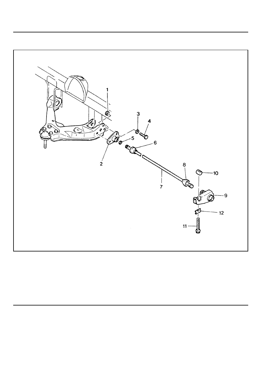
TORSION BAR
1 Nut
2 Torque Arm
3 Washer
4 Bolt . . . . . . . . . . . M10 : 40-60 Nm
M12 : 60-80 Nm
5 Torsion Bar End Seat
6 Dust Cover
7 Torsion Bar
8 Dust Cover
9 Height Control Arm Assembly
10 Height Control Bolt End Piece
11 Height Control Bolt
12 Height Control Seat
FRONT SUSPENSION 2C-7
Removal & Installation Procedure
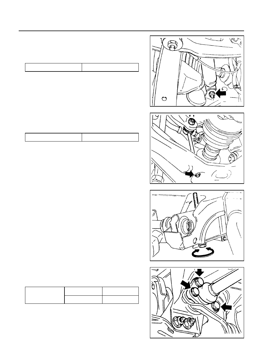
1. Remove the fixing nuts and bolts of the shock absorber
and lower arm connection.
Installation Notice
2. Remove the connecting nuts of the stabilizer bar link to the
lower arm.
Installation Notice
3. Turn the height control bolt until the distance between the
end of the height control bolt end piece and the bolt end
becomes 0-5 mm.
Installation Notice
Install the torsion bar spring and adjust the distance between
the end of the height control bolt and piece end the bolt
end to be 50-55 mm. Adjust the vehicle height.
Tightening Torque
60 - 80 Nm
Tightening Torque
16 - 22 Nm
4. Remove the torque arm fixing nuts and bolts and then
withdraw the torsion bar spring.
Installation Notice
M10
M12
Tightening Torque
40 - 60 Nm
60 - 80 Nm
5. Installation should follow the removal precedure in the
reverse order.
6. Check and adjust the wheel alignment.
2C-8 FRONT SUSPENSION
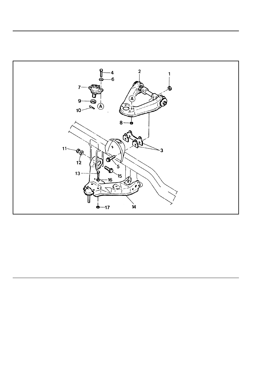
FRONT LOWER AND UPPER ARM
1 Nut . . . . . . . . . . . . ... 120-140 Nm
2 Fulcrum Pin and Upper Arm Assembly
3 Camber/Caster Adjusting Shim
4 Bolt
5 Bolt
6 Washer
7 Upper Arm End
8 Nut . . . . . . . . . . . . . ... 16-22 Nm
9 Castle Nut . . . . . . . . . . .. 80-150 Nm
10 Cotter Pin . . . . . . . . . . . ... Replace
11 Nut . . . . . . . . . . . . ... 150-180 Nm
12 Washer
13 Bolt
14 Lower Arm Assembly and Lower Arm End
15 Bolt
16 Washer
17 Nut . . . . . . . . . . . . . ... 60-80 Nm
Preceding Work : Removal of the torsion bar spring
Removal of the steering knuckle and drive shaft
Нет комментариевНе стесняйтесь поделиться с нами вашим ценным мнением.
Текст