SsangYong Musso. Manual — part 313
1F1-10 M162 ENGINE CONTROLS
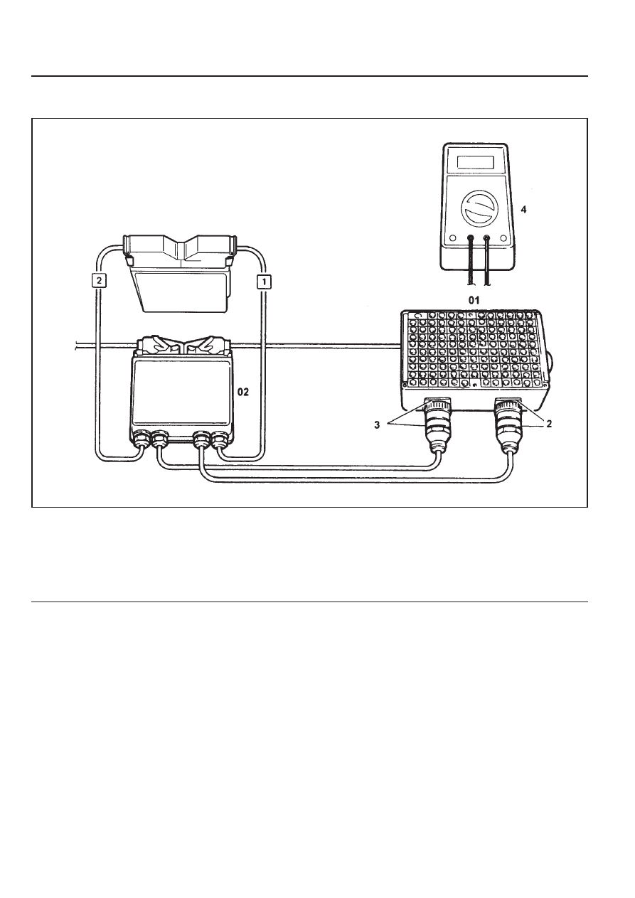
TEST BOX CONNECTION
1 ECU
2 Test Coupling(No.1 - 60)
3 Test Coupling(No.61 - 120)
4 Multi-tester
01 Test Box
02 ECU Test Cable
Tools Required
129 589 00 21 00 Test Box
210 589 08 63 00 ECU Test Cable
M162 ENGINE CONTROLS 1F1-11
FUEL INJECTION SYSTEM TEST (MSE3.62)
Failure
code
Item
⇒
1.0
Checking method
•
Ignition:ON
Test
step
Requirement
Specified
value
Possible cause
10
12
11 -14V
•••••
ECU:power
supply
- terminal
30(TM.30)
⇒
2.2
•••••
Power
supply:
- terminal
87(TM.87)
•
Ignition:ON
•
Power supply cable
•
OVPR
08,
•
⇒
1.1
•
⇒
1.2
⇒
1.1
•
Ignition:ON
10
2
11 -14V
•••••
Ground
cable:
- Battery
ground
•
Ground cable
•
Ground condition
Diagnosis
socket
69
2
Diagnosis
socket
⇒
1.2
•
Ignition:ON
1
12
11 -14V
•••••
Power
supply:
- terminal
30(TM.30)
•
Power supply cable
Diagnosis
socket
⇒
2.0
•
Ignition:ON
5
11
11 -14V
•••••
ECU:power
supply
- terminal
87(TM.87)
08,
•
⇒
1.1
•
⇒
2.1
⇒
2.1
•
Ignition:ON
11 -14V
•••••
Ground
cable
- Electronic
ground
•
Ground cable
5
2
Diagnosis
socket
1
11
Diagnosis
socket
•
Ignition:OFF
11 -14V
< 1V
⇒
3.0
•
Engine:in Cranking
5
2
•
Cable
•
Ignition switch
11 -14
(during engine
cranking)
•••••
Start signal:
- terminal
50(TM.50)
1F1-12 M162 ENGINE CONTROLS
Failure
code
Item
09,
10,
11,
Checking method
Test
step
Requirement
Specified
value
Possible cause
⇒
4.0
•••••
HFM sensor
signal
105
81
•
Ignition:ON
0.9 - 1.1V
•
⇒
4.1 - 4.3
•
Cable
•
External air inflow
•
HFM sensor
•
Engine:in Idle
(Coolant temperature
: > 70
°
C )
: voltage value is
increased when
engine rpm is
increased
1.3 - 1.7V
⇒
4.1
105
4
•
Ignition:ON
•
HFM sensor
connector removed
4.7 - 5.2V
•
Cable
•
ECU coupling
•••••
HFM sensor:
- 5V power
supply
HFM
sensor
⇒
4.2
3
108
•
Ignition:ON
•
HFM sensor
connector removed
4.7 - 5.2V
•
⇒
4.3
•
Cable
•••••
HFM sensor:
- 5V power
supply
HFM
sensor
⇒
4.3
104
2
•
Ignition:ON
•
HFM sensor
connector removed
11 - 14V
•
Cable
•
OVPR
•••••
HFM sensor:
- 12V power
supply
HFM
sensor
03,
04,
05,
⇒
5.0
•••••
Intake air
temperature
sensor:
- Voltage
105
80
•
Ignition:ON
•
⇒
5.1
•
ECU
±
5%
⇒
5.1
•
Ignition:OFF
•
No.2 ECU coupling
removed
105
80
•
Cable
•
HFM sensor
•••••
Intake air
temperature
sensor:
- Resistance
°
C
10
20
30
40
50
60
±
5%
Ω
3600
2420
1662
1166
853
600
°
C
10
20
30
40
50
60
V
3.1
2.65
2.18
1.76
1.4
1.1
M162 ENGINE CONTROLS 1F1-13
Failure
code
Item
Checking method
Test
step
Requirement
Specified
value
Possible cause
⇒
6.1
•
Ignition:ON
0.1 - 0.3A
•
Cable
•
Fuel pump relay
•
ECU
•••••
Fuel pump
relay:
- Current
consumption
00,
01,
02,
06,
⇒
7.0
•••••
Coolant
temperature
sensor:
- Voltage
79
78
•
Ignition:ON
°
C
V
20
3.57
80
1.22
100
0.78
•
⇒
7.1
•
ECU
±
5%
⇒
6.0
•
Ignition:ON
(Fuel pump relay will
operate for 1 - 2
seconds when the
ignition switch is
turned to "ON" after
stopping the engine)
•
Engine:cranking
33
11
•
Cable
•
Fuel pump relay
•••••
Fuel pump
relay:
- Operation
34,
11 - 14V
(approx.1-
2sec.)
11 - 14V
(Cranking or
driving)
5
33
⇒
7.1
•
Ignition:OFF
(Remove the No.2
coupling from ECU)
79
78
•
⇒
7.2
•
Cable
•••••
Coolant
temperature
sensor:
- Resistance
& cable
°
C
Ω
20 2500
80
322
100
185
±
5%
⇒
7.2
•••••
Coolant
temperature
sensor:
- Resistance
Coolant temperature
sensor:
1
4
•
Remove the
connector from
coolant temperature
sensor and measure
the resistance
between No.1 and
No.2 pin with
multimeter.
•
⇒
refer to
specified
resistance
value of 7.1
•
Coolant
temperature
sensor
34,
35,
Нет комментариевНе стесняйтесь поделиться с нами вашим ценным мнением.
Текст