SsangYong Musso. Manual — part 412

1E3-6 OM600 ENGINE ELECTRICAL
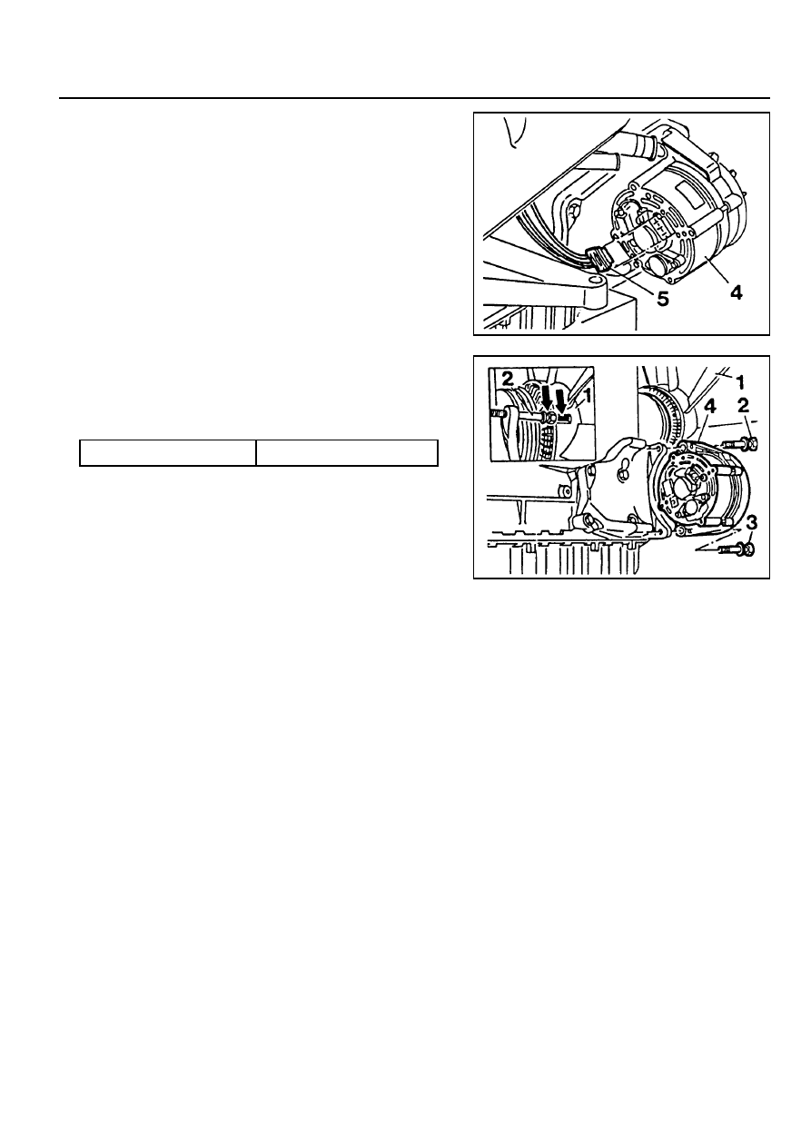
ALTERNATOR
Preceding Work : Removal of poly V-belt
1 Cooling Fan
2 Bolt . . . . . . . . . . . . . . . 45Nm
3 Bolt . . . . . . . . . . . . . . . 45Nm
4 Alternator
5 Plug Connection
OM600 ENGINE ELECTRICAL 1E3-7
Removal & Installation Procedure
1. Disconnect the negative terminal of the battery.
2. Disconnect the plug connection (5).
3. OM 662 Engine
Align the groove of cooling fan with bolt (2) (arrow).
4. Remove the bolts (2, 3) and take out the alternator.
5. Installation should follow the removal procedure in the
reverse order.
Tightening Torque
45 Nm
1E3-8 OM600 ENGINE ELECTRICAL
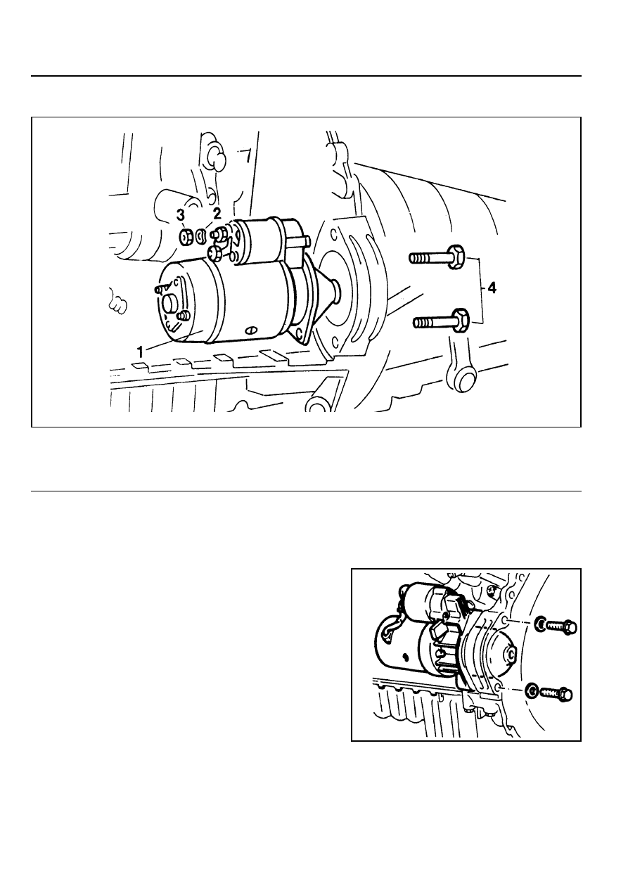
STARTER MOTOR
1 Starter Motor
2 Washer
3 Nut . . . . . . . . . . . . . . . . 15Nm
4 Bolt . . . . . . . . . . . . . . . 48Nm
Removal & Installation Procedure
1. Disconnect the battery terminals.
2. Disconnect the starter motor cable harnesses.
3. Remove the bolts and then remove the starter motor.
4. Installation should follow the removal procedure in the
reverse order.

SECTION 1F3
OM600 ENGINE CONTROLS
Specifications . . . . . . . . . . . . . . . . . . . . . . . 1F3-1
Fastener Tightening Specifications . . . . . . . . 1F3-1
Maintenance and Repair . . . . . . . . . . . . . . 1F3-2
On-Vehicle Service . . . . . . . . . . . . . . . . . . . . 1F3-2
Fuel System . . . . . . . . . . . . . . . . . . . . . . . . . 1F3-2
Fuel Injection Pump Coding . . . . . . . . . . . . . 1F3-3
Fuel Tank . . . . . . . . . . . . . . . . . . . . . . . . . . . 1F3-4
Vacuum Control System Test . . . . . . . . . . . . 1F3-5
Vacuum Pump(Sectional View) . . . . . . . . . . 1F3-10
Vacuum Pump Test . . . . . . . . . . . . . . . . . . . 1F3-11
Vacuum Pump . . . . . . . . . . . . . . . . . . . . . . 1F3-13
Vacuum Unit Replacement . . . . . . . . . . . . . 1F3-15
Idle Speed Adjustment . . . . . . . . . . . . . . . . 1F3-16
Fuel Pump Test . . . . . . . . . . . . . . . . . . . . . . 1F3-18
Fuel Pump . . . . . . . . . . . . . . . . . . . . . . . . . 1F3-21
Injection Nozzle Test . . . . . . . . . . . . . . . . . . 1F3-22
Injection Nozzles . . . . . . . . . . . . . . . . . . . . . 1F3-25
Injection Nozzle Repair . . . . . . . . . . . . . . . . 1F3-27
Removal and Installation of
Injection Timing Device . . . . . . . . . . . . . . 1F3-30
Injection Timing Device . . . . . . . . . . . . . . . . 1F3-35
Start of Delivery Test
(Position Sensor, RIV Method) . . . . . . . . . 1F3-37
Fuel Injection Pump . . . . . . . . . . . . . . . . . . 1F3-46
TABLE OF CONTENTS
Caution: Disconnect the negative battery cable before removing or installing any electrical unit or when a
tool or equipment could easily come in contact with exposed electrical terminals. Disconnecting this cable
will help prevent personal injury and damage to the vehicle. The ignition must also be in LOCK unless otherwise
noted.
SPECIFICATIONS
FASTENER TIGHTENING SPECIFICATIONS
Application
Fuel Tank Mounting Nut
Fuel Pump Pressure Line
Fuel Injection Nozzle
Fuel Injection Pipe
Nozzle Tensioning Nut
Screw Plug
Left-Hand Thread Bolt
N·m
28 - 47
13
35 - 40
18
80
30
46
Нет комментариевНе стесняйтесь поделиться с нами вашим ценным мнением.
Текст