SsangYong Musso. Manual — part 222
SUSPENSION DIAGNOSIS 2A-11
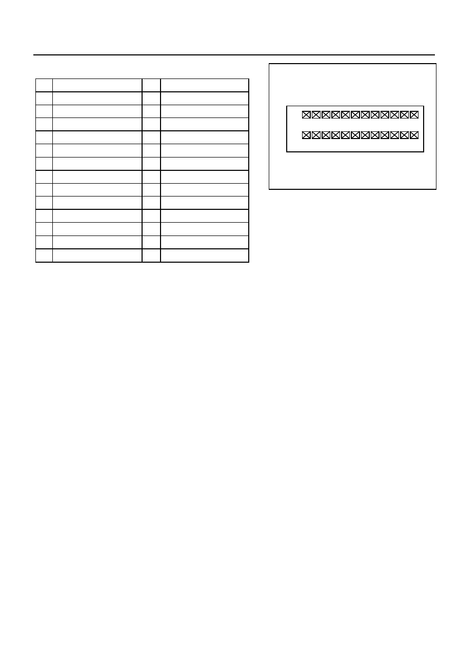
Connector Pin Number and Circuits
2
15
3
16
4
17
5
18
6
19
7
20
8
21
9
22
10
23
11
24
12
25
13
26
Ignition
Actuator R-MEDIUM
Actuator R-SOFT
Actuator F-HEAD
Select Switch
Speed Sensor
Wheel G Sensor
Wheel G Sensor Ground
-
Vertical G Sensor
Sensor +5V
Chassis Ground
Indicator Lamp
NO.
Circuit
NO.
Circuit
1
14
2
15
3
16
4
17
5
18
6
19
7
20
8
21
9
22
10
23
11
24
12
25
13
26
Chassis Ground
Actuator R-HEAD
Actuator F-MEDIUM
Actuator F-SOFT
Brake Switch
-
Lateral G Sensor
Lateral G Sensor Ground
Vertical G Sensor Ground
Diagnosis K Line
Diagnosis L Line
-
-
2A-12 SUSPENSION DIAGNOSIS
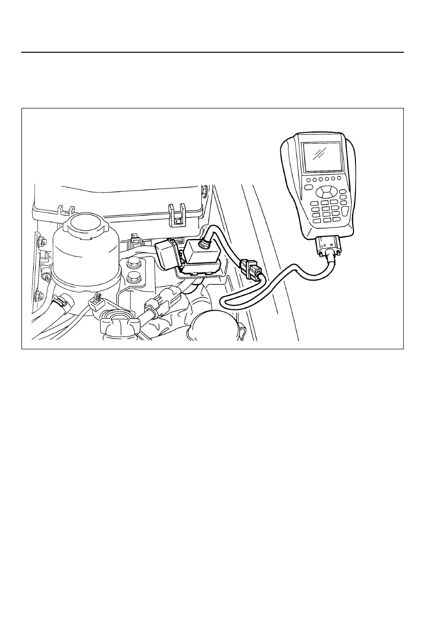
SELF DIAGNOSIS TEST
DIAGNOSIS TEST
Special Tool Requirements : Scanner
1. Position the ignition switch to 'OFF'.
2. Connect Scanner harness connector to the engine
compartment diagnosis socket.
3. Turn the ignition switch to 'ON' position.
4. Select "Electronic control vehicle diagnosis" from function
selection display and press "Enter".
5. Select "Musso ('98 model year)" from vehicle model selection
display and press 'Enter'.
6. Select "Electronic suspension system (ECS)" from control
system selection display and press 'Enter'.
7. Select "Self-diagnosis" from diagnosis item selection display.
Notice
Check sensor value output display, if necessary.
8. Determine the fault code and check defective component.
Notice
Refer to self-diagnosis list.
SUSPENSION DIAGNOSIS 2A-13
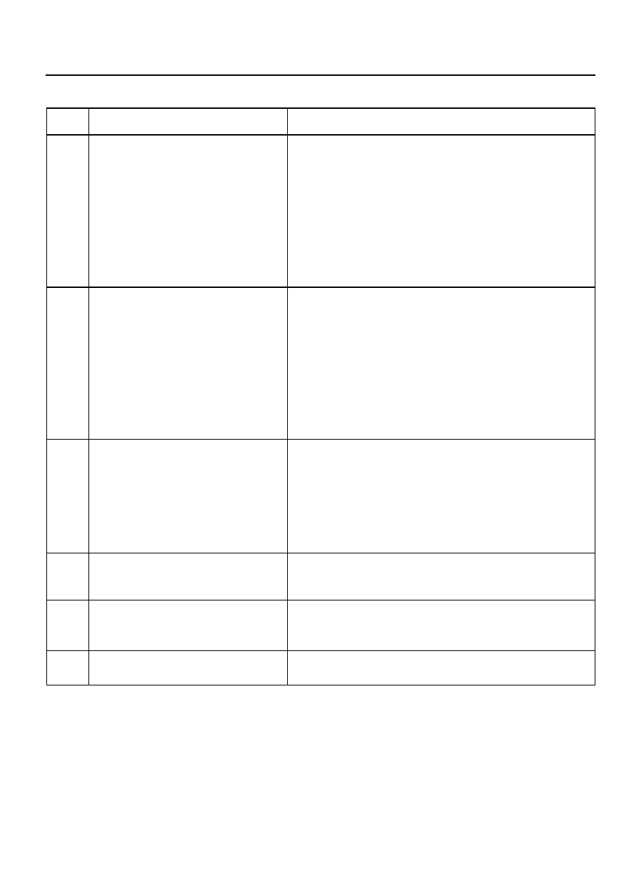
Self - Diagnosis List
Fault
Code
Defects
Service Hint
01
Vertical Acceleration Sensor
02
Lateral Acceleration Sensor
03
Wheel Acceleration Sensor
04
05
Rear Step Motor
06
ECU
Front Step Motor
1. Check sensor supply voltage
!
Condition - IGN ON
!
Standard value - voltage between pin 11 and 8 of ECU :
4.5 - 5.0V
2. Check sensor output voltage
!
Condition - IGN ON
!
Standard value - voltage between pin 20 and 11 of ECU
: 0.5 - 4.5V
3. Check the sensor.
4. Check circuit for open.
5. Check connection of other connectors.
1. Check sensor supply voltage
!
Condition - IGN ON
!
Standard value - voltage between pin 11 and 8 of ECU :
4.5 - 5.0V
2. Check sensor output voltage
!
Condition - IGN ON
!
Standard value - voltage between pin 10 and 11 of ECU
: 0.5 - 4.5V
3. Check the sensor.
4. Check circuit for open.
5. Check connection of other connectors.
1. Check step motor supply voltage.
2. Check circuit for open.
3. Check connection of other connectors.
1. Check step motor supply voltage.
2. Check circuit for open.
3. Check connection of other connectors.
1. Check connectors of ECU.
2. Replace the ECU.
1. Check sensor supply voltage
!
Condition - IGN ON
!
Standard value - voltage between pin 11, 8 and pin
7,11 of ECU : 4.5 - 5.0V
2. Check sensor output voltage
3. Check the sensor.
4. Check circuit for open.
5. Check connection of other connectors.

SECTION 2B
WHEEL ALIGNMENT
TABLE OF CONTENTS
SPECIFICATIONS
WHEEL ALIGNMENT SPECIFICATIONS
Application
Camber
Caster
Toe-in
King Pin Inclination
Description
0
° ±
30'
2
°
30'
±
30'
0 - 4 mm
12
°
30'
Specifications . . . . . . . . . . . . . . . . . . . . . . . . 2B-1
Wheel Alignment Specifications . . . . . . . . . . . 2B-1
Diagnosis . . . . . . . . . . . . . . . . . . . . . . . . . . . 2B-2
Tire Diagnosis . . . . . . . . . . . . . . . . . . . . . . . . . 2B-2
Radial Tire Lead/Pull . . . . . . . . . . . . . . . . . . . 2B-3
Vibration Diagnosis . . . . . . . . . . . . . . . . . . . . . 2B-5
Maintenance and Repair . . . . . . . . . . . . . . . 2B-6
On-Vehicle Service . . . . . . . . . . . . . . . . . . . . . . 2B-6
Wheel Alignment . . . . . . . . . . . . . . . . . . . . . . . 2B-6
General Description and System
Operation . . . . . . . . . . . . . . . . . . . . . . . . . 2B-9
Four Wheel Alignment . . . . . . . . . . . . . . . . . . 2B-9
Toe . . . . . . . . . . . . . . . . . . . . . . . . . . . . . . . . . 2B-9
Caster . . . . . . . . . . . . . . . . . . . . . . . . . . . . . . . 2B-9
Camber . . . . . . . . . . . . . . . . . . . . . . . . . . . . . . 2B-9
Нет комментариевНе стесняйтесь поделиться с нами вашим ценным мнением.
Текст