SsangYong Musso. Manual — part 524

TRANSFER CASE (TOD) 5D2-43
Disassembly Procedure
1. Disconnect transfer case from vehicle
2. Using a 30mm thin-wall socket, first remove the rear output
nut, output shaft yoke washer, oil seal then the case flange.
Installation Notice
27
Nut
28
Washer
30
Case Flange
Tightening Torque
137 - 196 Nm
3. Disconnect shift motor/clutch coil connector and speed
sensor connector from upper bracket of transfer case.
Notice
When disconnect connector, pull forwards grasping
connector housing.
4. Remove outer tube on speed sensor connector.
5. Remove wire supporting cape back side of speed sensor
connector.
6. Disconnect pin of clutch coil wire (yellow) from speed sensor
connector (white 7 pin) using long-nose plier.
7. Remove shift motor.
Notice
When remove shift motor, pay attention to the location of
triangular slot and shaft in transfer case inside motor.
8. Disconnect front and rear speed sensor.
5D2-44 TRANSFER CASE (TOD)
9.
Remove the bolts that retain the front case to the
rear case. Make sure that the front case is facing
downward so that the rear cover is facing upwards.
Pry on the bosses and separate the front case from
the rear case. Remove all traces of gasket sealant
from the mating surfaces of the front case and rear
case.
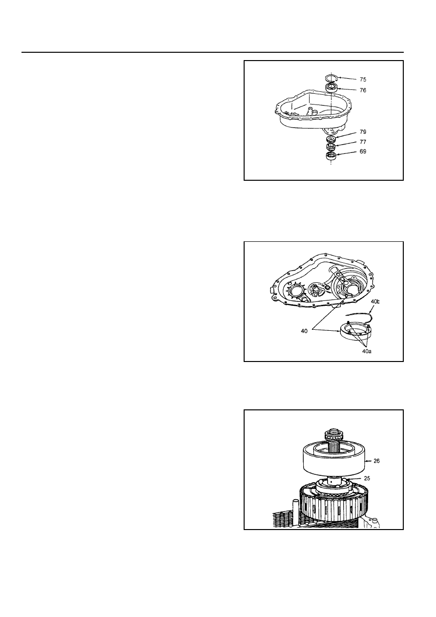
10. If the speedometer drive gear is to be replaced, first
remove the flange seal by prying and pulling the
curved-up lip of the flange seal. Do not damage the
bearing, bearing cage or case. Remove and discard
the flange seal. Remove the speedometer drive gear
and upper tone wheel.
69
Yoke to Flange Seal
75
Snap Ring
76
Bearing
77
Speedometer Drive Gear
79
Upper Tone Wheel
40
Clutch Coil
40a
Clutch Coil Retaining Bolts
40b
Wire
11. If the rear output shaft bearing requires replacing, remove
the internal snap ring that retains the bearing in the bore.
From the outside of the case, drive out the bearing.
12. Remove the three nuts and washers retaining the clutch
coil assembly to the rear case. Pull the assembly, along
with the O-ring and wire, from the case.
13. Remove bearing assembly from output shaft.
Remove the clutch housing from the output shaft.
Remove the balls and apply cam and wave washer from
the output shaft.
Remove snap ring from output shaft. Remove clutch pack
assembly from output shaft.
25
Ball
26
Cam and Coil Assembly
TRANSFER CASE (TOD) 5D2-45
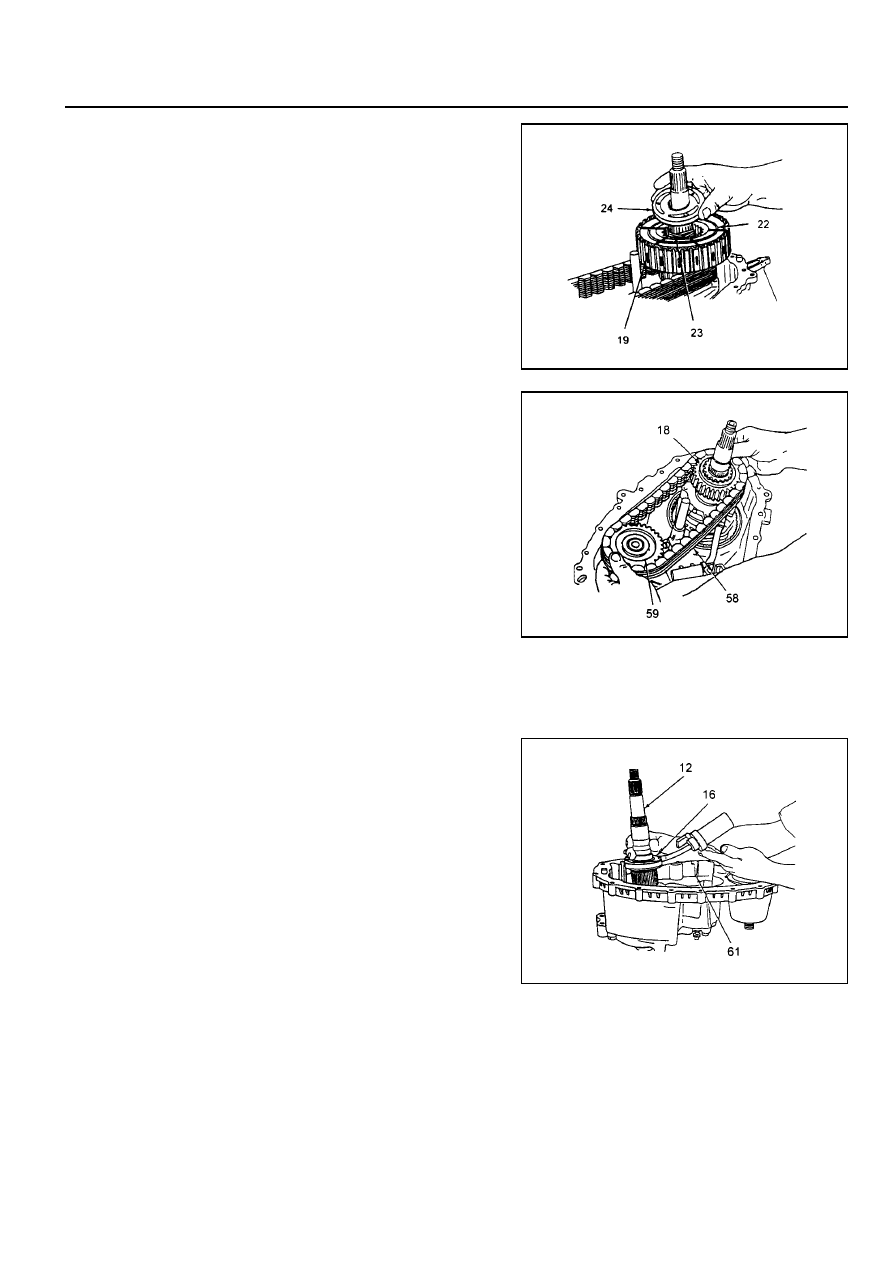
19
Clutch Pack Assembly
22
Snap Ring
23
Wave Washer
24
Apply Cam
14. Remove the chain, driven sprocket and drive sprocket
as an assembly.
15. Remove thrust washer from output shaft.
16. Remove the magnet from the slot in the front of the case
bottom. Remove the output shaft and oil pump as an
assembly.
Notice
If there is removal resistance, do not pound or use force
to disassemble the pump.
17. If required, to remove the pump from the output shaft,
rotate the pump to align.
18. Pull out the shift rail.
18
Drive Sprocket
58
Drive Chain
59
Driven Sprocket
12
Rear Output Shaft
16
Oil Pump
61
Magnet
19. Remove the helical cam from the front case. If required,
remove the helical cam, torsion spring and sleeve from
the shaft.
20. Remove the high-low range shift fork and collar as an
assembly.
21. Expand the tangs of the large snap ring in the case. With
the input shaft against a bench, push the case down and
slide the main drive gear bearing retainer off the bearing.
Lift the input shaft and front planet from the case.
22. If required, remove the oil seal from the case by prying
and pulling on the curved-up lip of the oil seal. Do not
damage the bearing, bearing cage or case.
5D2-46 TRANSFER CASE (TOD)
23. Remove the internal snap ring from the planetary carrier
and separate the front planet from the input shaft.
24. Remove the external snap ring from the input shaft. Place
the input shaft in a vise and remove the bearing. Remove
the thrust washer, thrust plate and the sun gear off the
input shaft.
25. Inspect the bushing and needle bearing in the end of the
input shaft for wear or damage.
Notice
Under normal use, the needle bearing and bushing should
not require replacement. If replacement is required, the
bushing and needle bearing must be replaced as a set.
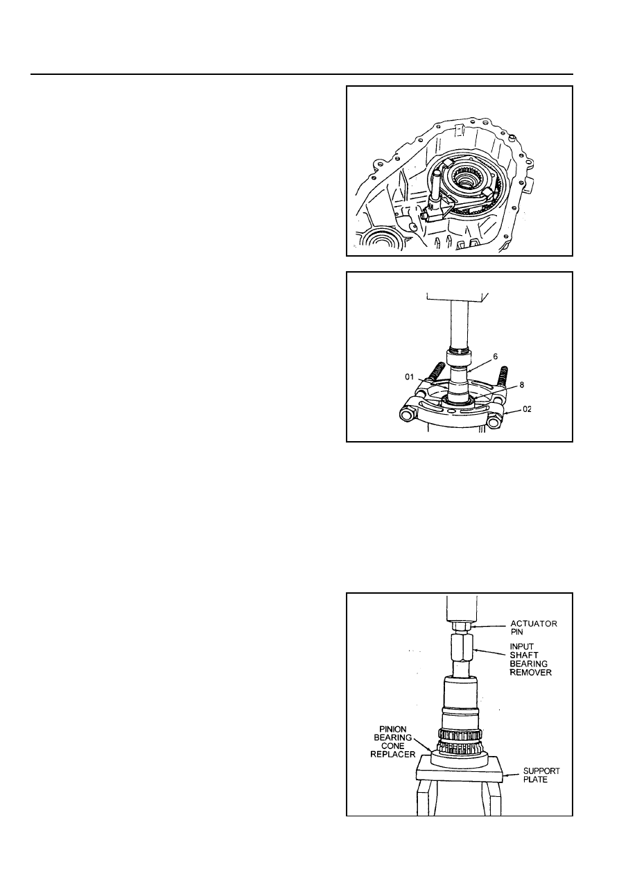
26. If replacement of the needle bearing and bushing is
required, press the bearing and bushing is required, press
the bearing and bushing out as follows:
a. Position the input shaft on Axle Bearing/Seal plate,and
using Pinion Bearing Cone Replacer as a spacer.
b. Insert Input Shaft Bearing Remover into the input shaft
so it is resting on top of the bearing cage.
c. Tighten the actuator pin until it stops, then press the
bearing and bushing out together.
6
Input Shaft
8
Bearig
01
Pinion Bearing Cone Remover
02
Compress the Dowel
27. If required, remove the front yoke to flange seal by prying
and pulling on the curved-up lip of the yoke to flange seal.
Do not damage the bearing, bearing cage or case.
28. If required, remove the internal snap ring retaining the
front output shaft ball bearing and remove the bearing.
Нет комментариевНе стесняйтесь поделиться с нами вашим ценным мнением.
Текст