SsangYong Musso. Manual — part 338

M161 ENGINE CONTROLS 1F2-31
Failure
code
Item
Checking method
Test
step
Requirement
Specified
value
Possible cause
1 liter of fuel
supply for
max. 35
seconds
•••••
Fuel pump:
- Fuel supply
ratio
•
Ignition:ON
- Disconnect the fuel
return pipe and
connect the host to
beaker to collect
the supplied fuel
⇒
1.0
•
⇒
2.0
•
Fuel line
5 - 9 A
•••••
Fuel pump:
- Current
consumption
•
Ignition:ON
- Remove the fuel
relay from the fuse
and relay box in
luggage
compartment and
connect the
amperemeter
between No.1 and
No.3 in relay
box(fuel pump relay
removed position)
for measuring
current
consumption
⇒
2.0
•
Fuel pump
5
33
Multi tester(DC current)
3
1
1F2-32 M161 ENGINE CONTROLS
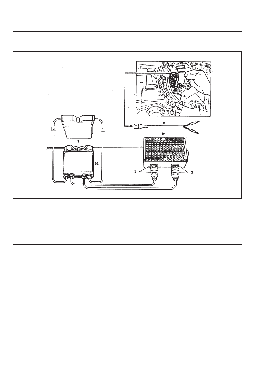
INJECTOR TEST
1 ECU
2 Test Coupling(No.1-60)
3 Test Coupling(No.61-120)
4 Measuring Beaker
5 Shop Made Cable
Preparation
03 Test Box
04 ECU Test Cable
Connection of the Equipment
1. Connect the test box to the ECU as shown in the figure.
2. Remove the 2-pin coupling from injector.
3. Remove the fuel distributor and injector with a unit. At this
time, do not remove the supply and return line.
4. Connect the shop made cable to the injector with a firing
order.
5. Collect the fuel from injector.
Tools Required
129 589 00 21 00 Test Box
210 589 08 63 00 ECU Test Cable
M161 ENGINE CONTROLS 1F2-33
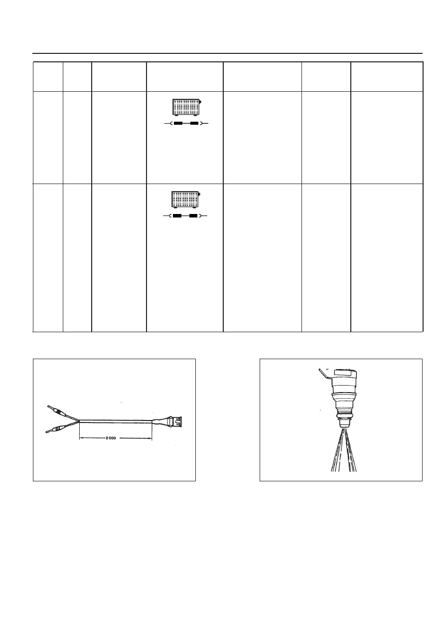
Figure 8. Shop Made Cable
Figure 9. Fuel Injector Normal Spary Pattern
Failure
code
Item
Checking method
Test
step
Requirement
Specified
value
Possible cause
There should
be no leaks
and later
drops from
the injector
•••••
Injector:
- Leakage
test
•
Ignition:ON
- Remove the fuel
distributor and fuel
injector with a unit.
⇒
1.0
•
⇒
2.0
•
Injector
The spray
pattern of the
injector most
show in the
figure 10
•
Ignition:ON
- Connect the shop
made cable to the
injector.
- Collect the
spraying fuel with a
beaker
- Connect the shop
made cable to
No.11(+) and No.5
(-) terminal in test
box.
⇒
2.0
•
Injector
5
33
•••••
Injector:
- Function
test and
spray
pattern
check
5
33

1F2-34 M161 ENGINE CONTROLS
MAINTENANCE AND REPAIR
ON-VEHICLE SERVICE
ECU
Appearance
1 Cover
2 Plate
3 Connector
4 Flat pin
Vehicle side : number 1 - 12
Engine side : number 61 - 72
5 Pin
Vehicle side : number 13 - 60
Engine side : number 73 - 120
A Vehicle Connector : Black
B Engine Connector : Gray
Нет комментариевНе стесняйтесь поделиться с нами вашим ценным мнением.
Текст