SsangYong Musso. Manual — part 326
1F1-62 M162 ENGINE CONTROLS
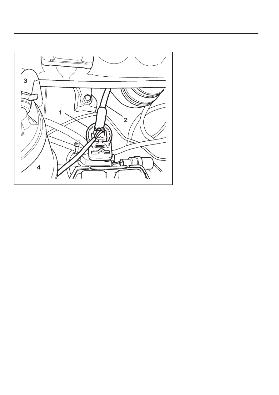
PURGE SWITCHOVER VALVE
1 Purge Switchover Valve
2 Line to Engine
3 Line to Canister
4 Canister
Functions
The fuel vaporization control system is installed to inhibit the
fuel vaporized gas from discharging into the atmosphere. The
fuel vaporized gas that is accumulated in the canister abstracts
through the purge switchover valve purification during the
engine combustion (except the decreasing mode) and coolant
temperature of over 80
°
C. For this reason, the ECU transacts
the engine speed, air inflow quantity, coolant temperature, and
intake temperature.
The purge switchover valve is activated by the ECU frequency
according with the engine rotating speed to adjust the
purification rate. The purification rate is determined by the
continuous valve opening interval.
The purge switchover valve is activated by the ECU for the
following conditions :
z
Coolant temperature of over 80
°
C
z
Engine speed of over 1000rpm
z
2 Minutes after starting
z
When the fuel cut-off mode is not activated
M162 ENGINE CONTROLS 1F1-63
4. Remove the line to canister and measure the pressure with
the vacuum pressure gauge.
Test
1. Maintain the normal temperature and idling state by
operating the engine.
2. Connect the ECU terminal No.11 and No.34 and check for
normal operation through the output waves using the
scanner.
Notice
Test during purge control switchover valve operation after
the minimum of 1 minute after the engine turned on.
3. Connect the ECU terminal No.34 and No.10 and check for
current consumption during the ignition switch ON.
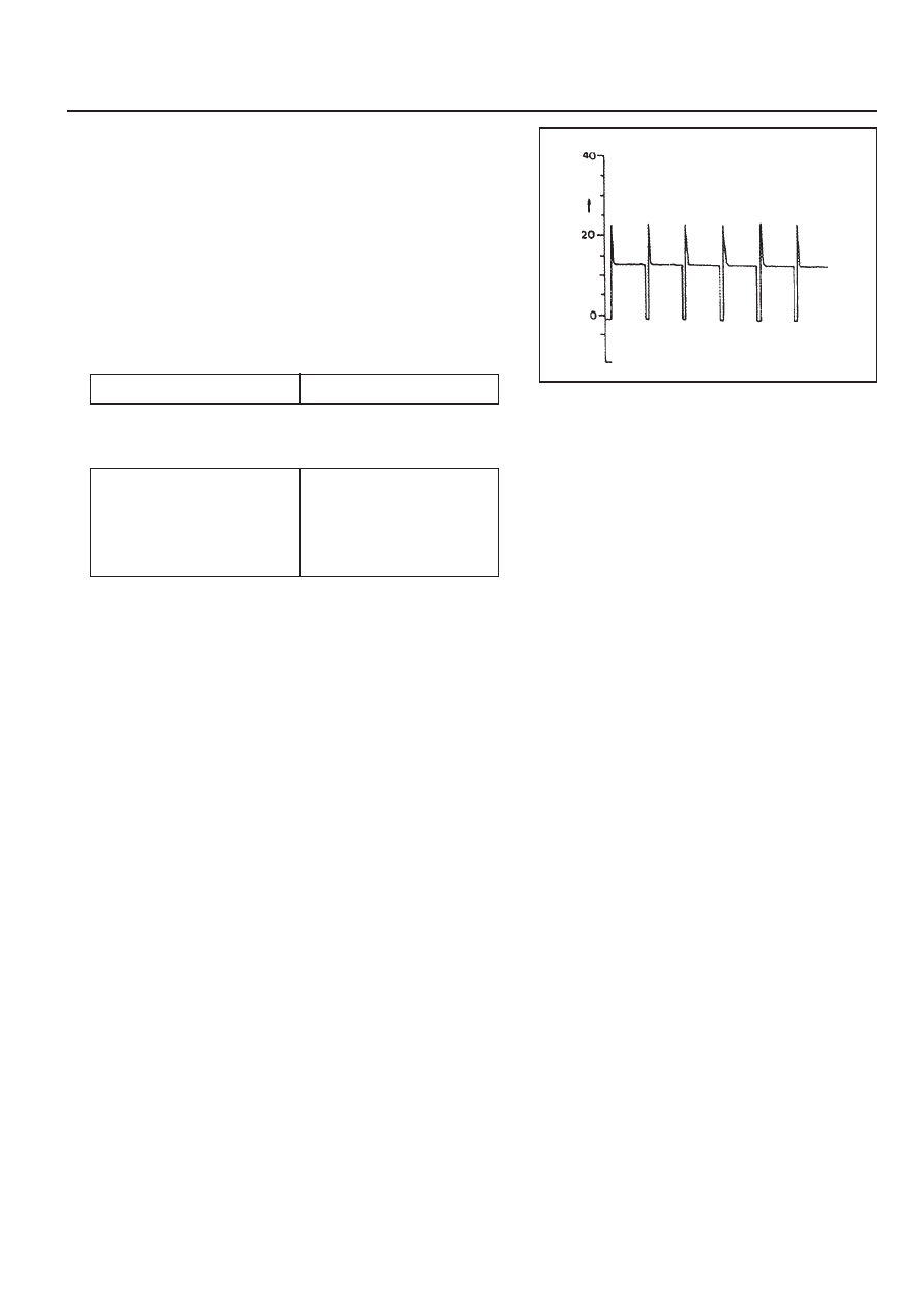
Purge switchover valve output wave
Specified Value
0.3 - 0.5
Specified Value
> 50mbar
(after approx. 1min.)
purge switchover valve
operates at this time
Notice
Test while at normal temperature and at idling state by
operating the engine.

1F1-64 M162 ENGINE CONTROLS
VACUUM SYSTEM
1 Purge Control Valve
2 Molded Hose
3 Insulator
4 Fuel Tube
5 Molded Hose
6 Idle Regulator
7 Resonance Flap
8 Intake Manifold
9 Fuel Pressure Regulator
10 Vacuum Line Rubber Hose
11 Vacuum Tube(Gray, 270mm)
12 Molded Hose
13 Rubber Cap
18 Rubber Hose
19 Vacuum Tube(Brown or Black, 770mm)
20 Rubber Hose
A To Canicter
M162 ENGINE CONTROLS 1F1-65
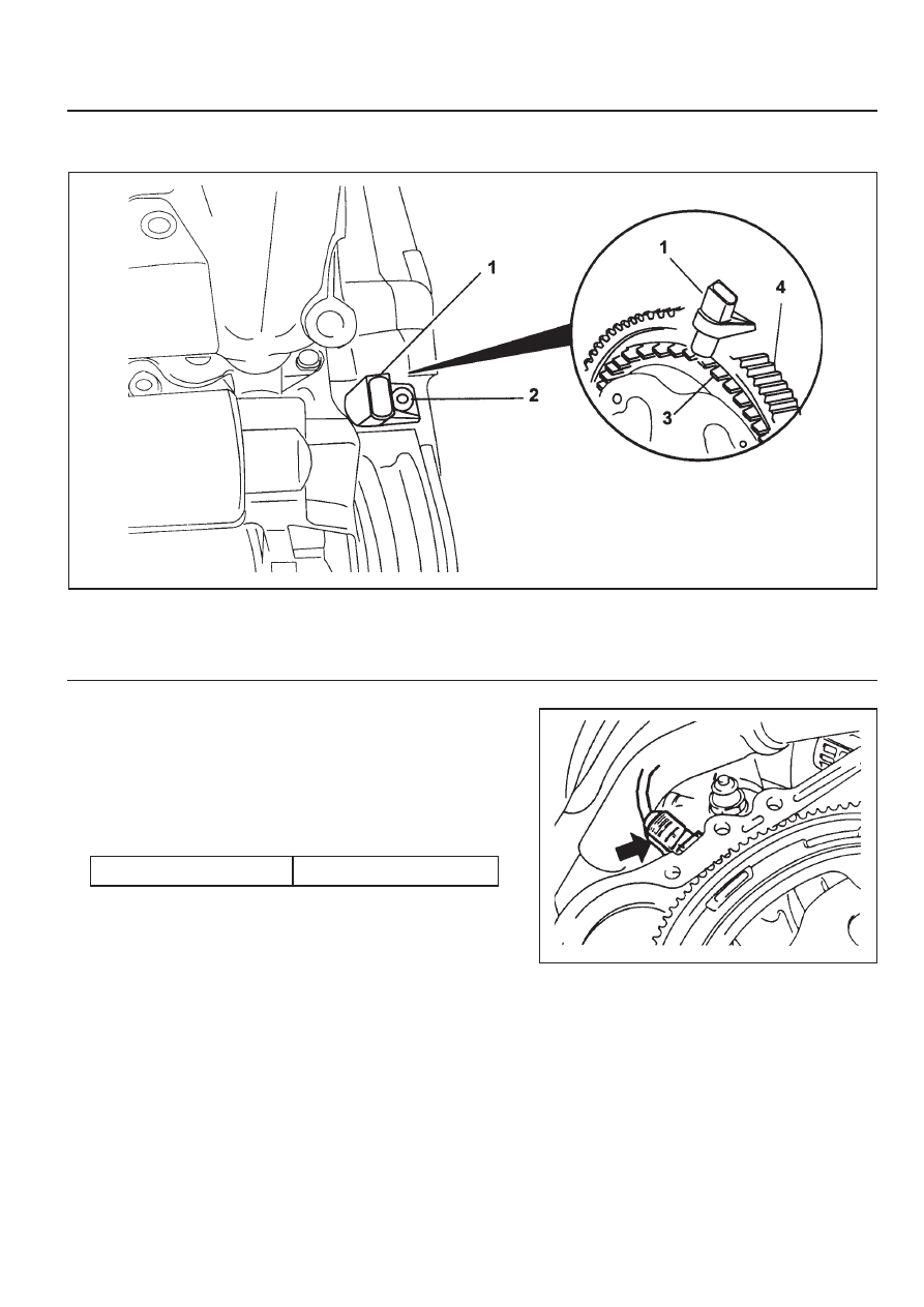
1 Crankshaft Position Sensor
2 Bolt (M6 X 14) . . . . . . . . . . 9 -11Nm
CRANKSHAFT POSITION SENSOR
Removal & Installation Procedure
1. Disconnect the wiring connector at the crankshaft position
sensor.
2. Unscrew the bolt and remove the crankshaft position sensor
unit.
Installation Notice
3. Installation should follow the removal procedure in the
reverse order.
3 Segment
4 Flywheel
Tightening Torque
9 -11Nm
Нет комментариевНе стесняйтесь поделиться с нами вашим ценным мнением.
Текст