SsangYong Musso. Manual — part 460
AUTOMATIC TRANSMISSION 5A-17
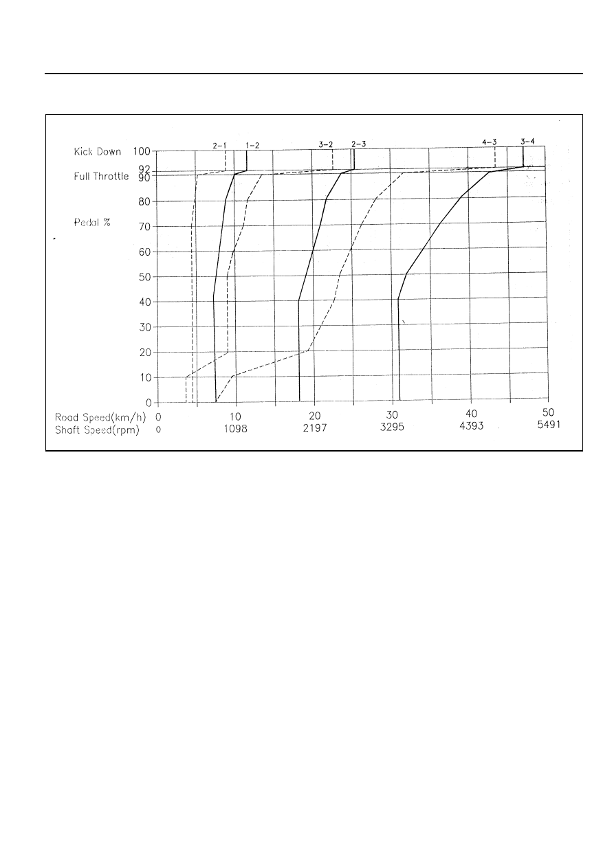
E23 LOW MODE
5A-18 AUTOMATIC TRANSMISSION
INTRODUCTION
The BTR Automotive Model 74 Four Speed Automatic Transmission is an electronically controlled overdrive four
speed unit with a lock-up torque converter. The lock-up torque converter results in lower engine speeds at cruise and
eliminates unnecessary slippage. These features benefit the customer through improved fuel economy and noise
reduction. Refer to table 1.1 for details of power, torque and configuration.
Of primary significance is the transmission control unit (TCU) which is a microprocessor based control system. The
TCU utilizes throttle position, rate of throttle opening, engine speed, transmission output speed, transmission sump
temperature, gear selector position and mode selector inputs, and in some applications a ‘kickdown’ switch to control
all shift feel and shift schedule aspects.
The TCU drives a single proportional solenoid multiplexed to three regulator valves to control all shift feel aspects.
The output pressure of this solenoid is controlled as a function of transmission sump temperature to maintain consistent
shift feel throughout the operating range.
Shift scheduling is highly flexible, and several independent schedules are programmed depending on the vehicle.
Typically the ‘NORMAL’ schedule is used to maximise fuel economy and driveability, and a ‘POWER’ schedule is used
to maximise performance. ‘WINTER’ schedule is used to facilitate starting at second gear.
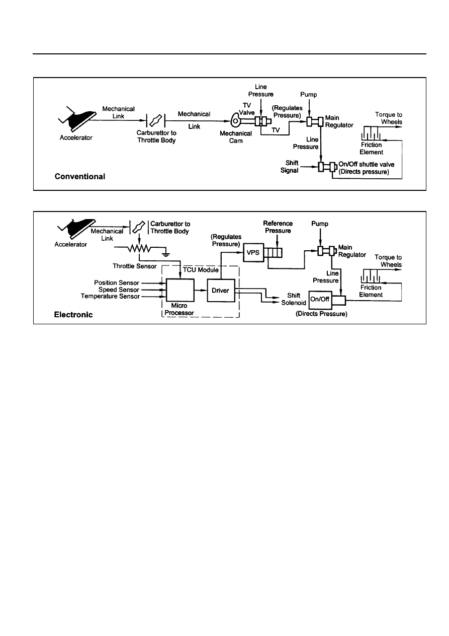
Figure 1.1 details the differences between conventional and electronic transmission control systems.
Max Torque (Nm)
320
Configuration
260 mm Torque Converter
Wide Ratio Gear Set
Splined Output for Transfer Case
Min Torque (Nm)
160
Model
M74 4WD
Transmission
Table 1.1 - M74 Torque, Power and Configuration
AUTOMATIC TRANSMISSION 5A-19
Figure 1.1 - Conventional VS Electronic Transmission Control System

5A-20 AUTOMATIC TRANSMISSION
OPERATOR INTERFACES
There are three operator interfaces associated with the four speed transmission.
They are:
!
The gear select lever
!
The driving mode selector
!
The indicator light
These operator interfaces are described below.
GEAR SELECT LEVER OPERATION
The transmission uses a conventional selector lever. The selector lever can be moved from one position to another
within the staggered configuration of the selector lever gate to positively indicate the gear -selection as shown on
figure 2.1. For information about the gear selections available refer to table 2.1.
Figure 2.1 - Typical Gear Selector and Mode Switch
Нет комментариевНе стесняйтесь поделиться с нами вашим ценным мнением.
Текст