SsangYong Musso. Manual — part 471

AUTOMATIC TRANSMISSION 5A-61
Pin
No.
9
10
11
12
13
14
15
16
17
18
19
20
21
22
23
24
25
26
27
28
29
30
Identification
Mode Indicator Lamp -
‘Power’
Throttle Position Sensor
Output as Pulse Width
Modulation for TOD
Air Conditioner Input Signal
Kickdown Switch
Mode Switch
Transfer Case Input
(High) -4WD Lamp High
Ignition Switch
Do not use
Gear Position ‘1’ Lamp/
Gear Position Code 1
*Gear Position ‘2’ Lamp/
Gear Position Code 2*
Gear Position ‘3’ Lamp/
Gear Position Code 3*
Gear Position ‘Drive’
Lamp/
Gear Position Code 4*
CAN (-ve)
CAN (+ve)
K-line Communication Link
Engine Speed Input
Sensor (+ve)
Road Speed Pulses
Shaft Speed Sensor
Signal
Throttle Position Sensor -
Ground
Throttle Position Sensor -
Reference
Throttle Position Sensor -
Input Signal
Transfer(or Case Input
(Low) - 4WD Lamp Low
Type
OP
OP
-
IP
IP
IP
IP
-
OP
OP
OP
OP
I/O
I/O
I/O
IP
OP
IP
GND
REF
IP
IP
Description
Indicates ‘POWER’ mode shift schedule is se-
lected.
Provides an analogue signal of the throttle po-
sition for the Torque on Demand (TOD) Con-
trol Module.
Input
Switch to indicate when a kickdown is required
at high throttle position.
Switch to select ‘NORMAL’, ‘POWER’ or ‘WIN-
TER’ shift schedule.
Voltage varies from OV to 12V.
Switch to indicate 4WD’HIGH RANGE’ is se-
lected.
Ignition power is used as the main power source
to drive the unit and the solenoids.
Drives jewel in the instrument cluster to indi-
cate
gear leverposition’1'. Drives jewel in the instru-
ment cluster to indicate
gear lever position’2'. Drives jewel in the instru-
ment cluster to indicate gear lever position’3'.
Drives jewel in the instrument cluster to indi-
cate
‘DRIVE’. gear lever position.
CAN low side bus communication (CANL).
CAN high side bus communication (CANH).
Diagnostic information and vehicle coding.
Flywheel/Ring gear pulses to indicate engine
speed.
Road speed signals derived from shaft speed
sensors.
This sensor transmit shaft speed signal to the
TCU.
Throttle position sensor ground.
This is the 5V reference voltage supply gener-
ated by the unit for the throttle position sensor.
This sensor is a resistance potentiometer indi-
cating throttle position.
Voltage varies 0V to 5V.
Switch to indicate 4WD’LOW RANGE’ is se-
lected.
4WD
(Diesel)
O
O
O
O
!
!
!
4WD
(Gas)
O
O
O
O
O
O
O
O
!
!
!
!
!
!
!
!
!
!
!
!
!
!
!
!
!
!
!
!
!
!
!
!
!
!
!
!
!

5A-62 AUTOMATIC TRANSMISSION
Identification
Gear Lever Position
Transmission Oil
Temperature
Solenoid 4
Solenoid 1
Do not use
Solenoid 5
Return (-ve)
Gear Lever Position -
Ground
Transmission Oil
Temperature - Ground
Solenoid 6
Solenoid 2
Solenoid 3
Solenoid 7
Do not use
Solenoid 5 (+ve)
Type
IP
IP
OP
OP
-
IP
GND
GND
OP
OP
OP
OP
-
OP
Description
This switch has discreet values indicating the
positions selected by the gear shift lever
(PRNDL). Voltage varies 0V to 5V.
Resistive sensor indicates transmission tem-
perature .
High R = low temp
Low R = high temp
Voltage varies 0V to 5V.
On/Off solenoid normally open, combines with
other On/off solenoid 3 for shift quality and se-
quencing.
On/off solenoid normally open, combines with
other On/off solenoid to set the selected gear.
This ensures the earth path for the VPS and
the current in this line is monitored to give feed-
back control of the VPS.
PRNDL switch ground.
Ground reference for temperature sensor in-
put.
On/Off solenoid normally open, sets low/high
line pressure.
On/off solenoid normally open, combines with
other On/off solenoid to set the selected gear.
On/off solenoid normally open, combines with
On/off solenoid 4 for shift quality and sequenc-
ing.
On/off solenoid normally open, locks up the
torque converter to Increase cruising efficiency.
This is the variable force solenoid which ramps
the pressure during gear changes and solenoid
switching, to enhance transmission shift quality.
4WD
(Diesel)
O
O
!
!
4WD
(Gas)
O
O
!
!
!
!
!
!
!
!
!
!
Pin
No.
31
32
33
34
35
36
37
38
39
40
41
42
43
44
!
!
!
!
!
!
!
!
!
!
!
!
!
= circuit connected
O
= circuit not connected
*
= unique
OP = Output
IP
= Input
I/O
= Input/output
GND = Ground
REF = Reference
Notice :
AUTOMATIC TRANSMISSION 5A-63
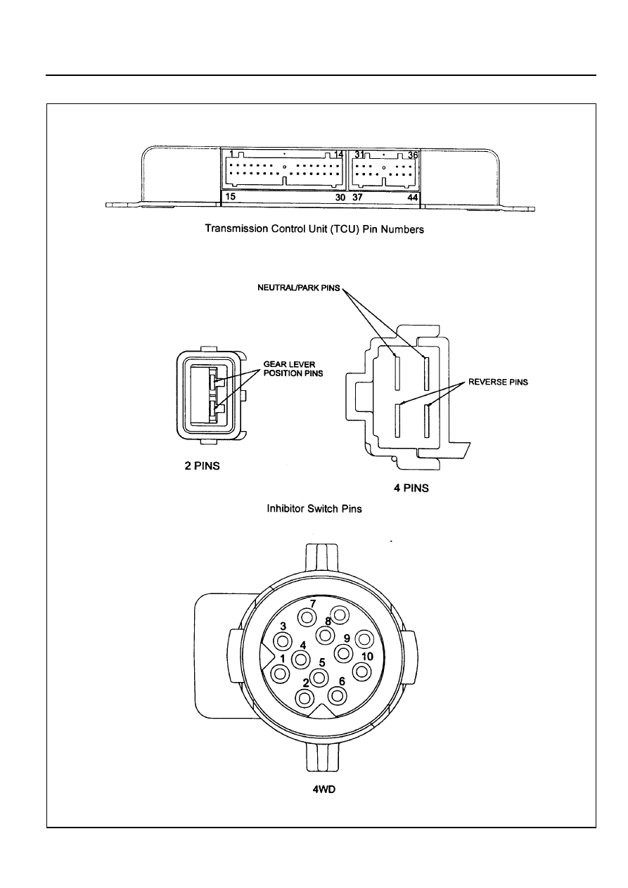
Ten Pin Plug Pin Numbers
Figure 6.1.1 - Wiring Loom Pins
5A-64 AUTOMATIC TRANSMISSION
Default Transmission Operating Modes
The TCU relies on accurate information from its inputs and complete control of its outputs to effectively control the
transmission. To ensure that it has both valid inputs and functioning outputs, the TCU carries out both hardware and
software fault detection routines. The TCU will respond to any faults detected by adopting the operating modes which
are detailed below.
The following symptoms of faults are the most obvious results of each fault under ‘normal’ conditions.
There is always the possibility that a fault may not be detected. If undetected fault conditions are present, the
operation of the transmission is difficult to predict.
1 Throttle Fault
!
All shifts will occur as if a nominal throttle (approx. 44%) were applied for shift scheduling.
!
All shifts will be firm as full throttle and hence high engine torque is assumed.
!
The torque converter will be unlocked at all times.
!
All downshifts initiated by the shift lever will occur as though they were ‘automatic’ shifts. That is the engine
braking effect will not occur until near the end of the shift.
!
Line pressure will always stay high (solenoid 6 OFF) to cope with assumed high throttle/torque.
If a fault is undetected, the percent throttle is most likely to be interpreted as higher than actual, resulting in late
upshifts, early downshifts, firm shifting and a harsh 3-1 shift when stopping.
2 Throttle Not Learnt Fault
The transmission operates from default throttle calibration values which results in the evaluation of the throttle being
higher (more open) than it is. There(ore at zero throttle settings, the transmission may calculate that sufficient throttle
opening is present to justify high line pressure and switch solenoid 6 to OFF.
Other symptoms are:
a. late upshifts and
b. lock-up maintained at zero throttle when the vehicle speed is sufficiently high.
3 Engine Speed Fault
!
All shifts will be firm because an engine speed corresponding to peak engine torques is assumed.
If a fault is undetected, the engine speed is likely to be interpreted as stalled resulting in soft shifting possibly with an
end of shift bump.
4 Vehicle Speed Sensor Fault
!
All shifts will be controlled by the shift lever with skip downshifts disabled and downshifts only allowed if the
engine speed is low. Fourth gear will be inhibited.
!
The torque converter will be unlocked at all times.
If a fault is undetected, the vehicle is likely to be interpreted as being stationary resulting in first gear operation at all
times. Note that speedometer transducer faults are likely to cause the vehicle’s speedometer to become inoperative.
5 Gear Lever Fault (Inhibitor/PRNDL Switch)
!
The gear lever is assumed to be in the Drive position.
!
The transmission is limited to 2nd,3rd, and R gears only.
!
The rear band will apply at all times when the lever is shifted to P, R or N. (B2 inhibition and reverse lockout
protection is disabled.)
!
The torque converter will be unlocked at all times.
!
Manually (gear lever) initiated downshifts will not be available.
If a fault is undetected, the gear lever position is likely to be interpreted as being higher than actual. Where Park is the
highest position and Manual 1 is the lowest, the result being the availability of higher gears than selected by the gear
lever.
Нет комментариевНе стесняйтесь поделиться с нами вашим ценным мнением.
Текст