SsangYong Musso. Manual — part 310

1E2-10 M161 ENGINE ELECTRICAL
Ignition Cable and Cable Lay-out
1. Firing Order : 1-3-4-2
2. T1/1 : Connect the cylinder 1 + 4
3. T1/2 : Connect the cylinder 2 + 3
Removal & Installation Procedure
1. Disconnect the battery negative cable.
2. Unscrew the 3 screws and remove the ignition cable duct
cover.
Installation Notice
3. Seperate the cable from the ignition cable and the spark
plug.
4. Remove the 2 bolts from each ignition cable and remove
the ignition cables.
Installation Notice
Install the ignition cable to the cylinder 2 and 4 and connect
the cable from 1 to 4, and from 2 to 3.
- T1/1 : Cylinder 1 and 4
- T1/2 : Cylinder 2 and 3
5. Installation should follow the removal procedure in the
reverse order.
Tightening Torque
9 - 11 Nm
Tightening Torque
9 - 11 Nm
M161 ENGINE ELECTRICAL 1E2-11
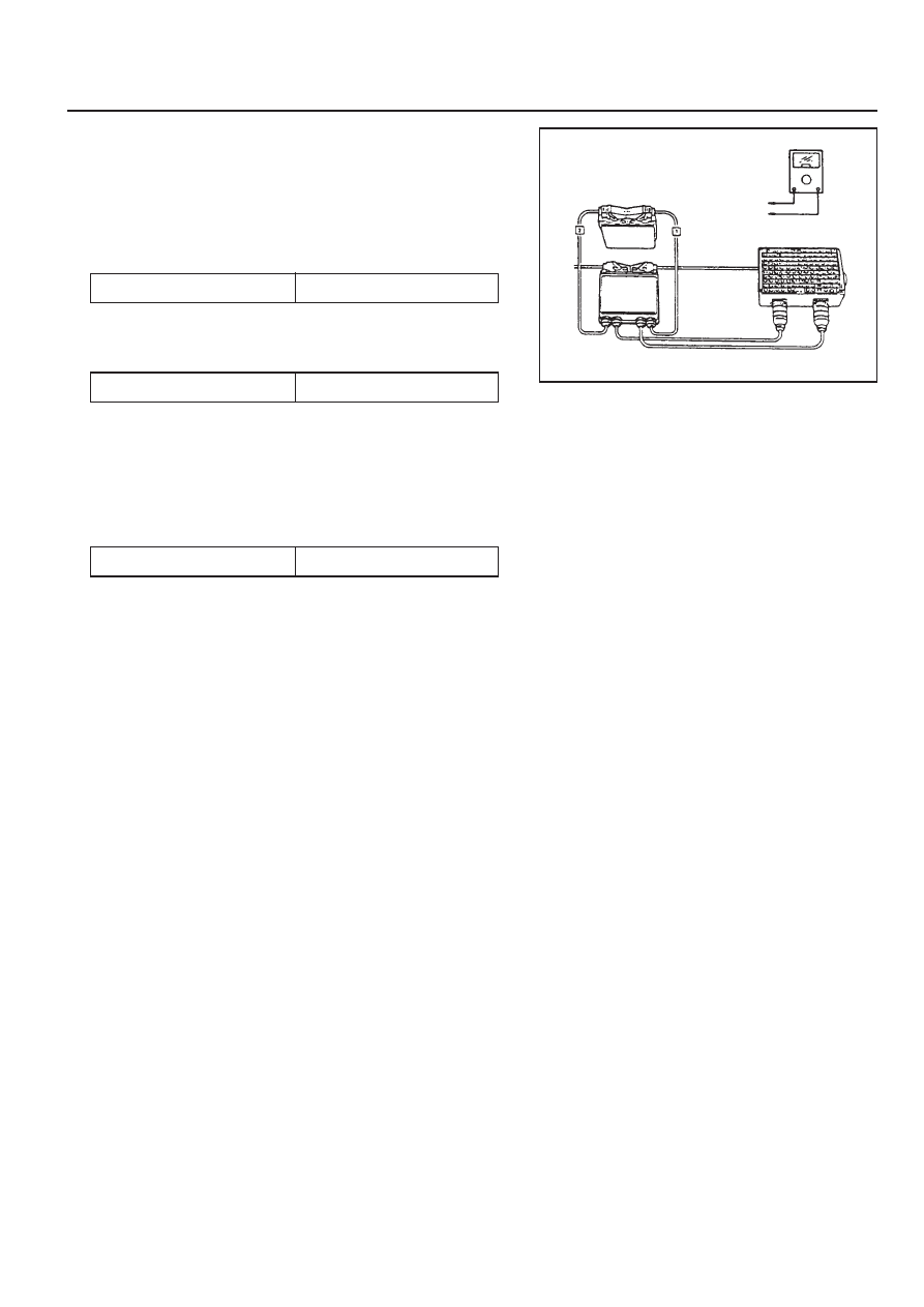
Inspection & Maintenance (for E2.3 MSE)
1. Measure the primary resistance between the cable terminals
1 and 15 after removing the ignition cable wiring connector
(1 and 15) with ignition switch OFF.
Notice
Replace the ignition coil if out of the specified resistance.
z
T1/2 : between No.71 and No.69
Notice
Check the ignition cable and the ECU if out of the
specified value.
3. Measure the secondary cable resistance between the
ignition coil 5a and 5b using a multimeter.
2. Measure the primary voltage(T1/1) between the ECU
terminals No.72 and No.69 during the engine cranking
(starter motor activated).
Specified Value
6 - 8.5 K
Ω
Specified Value
0.9 - 1.6
Ω
Specified Value
200 - 350 V
1E2-12 M161 ENGINE ELECTRICAL
UNIT REPAIR
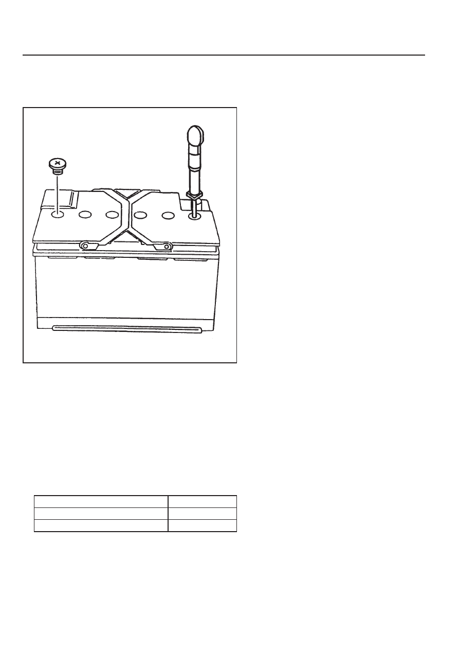
BATTERY
Inspection
Notice
z
When charging the battery, do not leave the inflammable
objects around it.
z
When checking the electrolyte of battery, put on
an eye protector and gloves.
1. Inspect the surface of the battery and replace if any defects
were found on it.
2. Check if the specific gravity of the electrolyte is within the
specified value.
Notice
z
Replace the battery if the maximum tolerance of the
electrolyte between cells is out of the specified value.
z
Measure the specific gravity in the approx. 20°C
of ambient temperature.
3. Replenish the electrolyte if necessary.
Battery Capacity(Ah)
Battery Specific Gravity
Max. Tolerance between Cells
75
≥
1.24
≥
0.04
SECTION 1F1
M162 ENGINE CONTROLS
TABLE OF CONTENTS
CAUTION: Disconnect the negative battery cable before removing or installing any electrical unit or when a
tool or equipment could easily come in contact with exposed electrical terminals. Disconnecting this cable
will help prevent personal injury and damage to the vehicle. The ignition must also be in LOCK unless otherwise
noted.
Specifications . . . . . . . . . . . . . . . . . . . . . . . 1F1-2
Fastener Tightening Specifications . . . . . . . . 1F1-2
Special Tools . . . . . . . . . . . . . . . . . . . . . . . 1F1-3
Special Tools Table . . . . . . . . . . . . . . . . . . . . 1F1-3
Schematic and Routing Diagrams . . . . . . . 1F1-4
E32 ECU (HFM) . . . . . . . . . . . . . . . . . . . . . . 1F1-4
E32 ECU (MSE) . . . . . . . . . . . . . . . . . . . . . . 1F1-5
Diagnosis . . . . . . . . . . . . . . . . . . . . . . . . . . 1F1-6
Self Diagnosis Socket Pin Numbers and
Descriptions . . . . . . . . . . . . . . . . . . . . . . . . 1F1-6
Self Diagnosis Failure Code . . . . . . . . . . . . . 1F1-7
Test Box Connection . . . . . . . . . . . . . . . . . . 1F1-10
Fuel Injection System Test (MSE3.62) . . . . . 1F1-11
Ignition System Test . . . . . . . . . . . . . . . . . . 1F1-21
Idling Control and Electronic Pedal
System Test . . . . . . . . . . . . . . . . . . . . . . . 1F1-26
Air Conditioner Control System Test . . . . . . 1F1-28
Fuel Pressure and Internal Leakage Test . . 1F1-29
Fuel Pump Test . . . . . . . . . . . . . . . . . . . . . . 1F1-31
Injector Test . . . . . . . . . . . . . . . . . . . . . . . . 1F1-33
Maintenance and Repair . . . . . . . . . . . . . 1F1-35
On-Vehicle Service . . . . . . . . . . . . . . . . . . . . 1F1-35
ECU . . . . . . . . . . . . . . . . . . . . . . . . . . . . . . 1F1-35
Fuel Pressure Regulator . . . . . . . . . . . . . . 1F1-46
Fuel Distributor . . . . . . . . . . . . . . . . . . . . . . 1F1-50
Injector . . . . . . . . . . . . . . . . . . . . . . . . . . . . 1F1-54
Fuel Filter . . . . . . . . . . . . . . . . . . . . . . . . . . 1F1-57
Fuel Pump . . . . . . . . . . . . . . . . . . . . . . . . . 1F1-58
Purge Switchover Valve . . . . . . . . . . . . . . . 1F1-62
Vacuum System . . . . . . . . . . . . . . . . . . . . . 1F1-64
Crankshaft Position Sensor . . . . . . . . . . . . 1F1-65
Camshaft Position Sensor . . . . . . . . . . . . . 1F1-67
Hot Film Air Mass (HFM) Sensor . . . . . . . . . 1F1-69
Oxygen Sensor . . . . . . . . . . . . . . . . . . . . . . 1F1-72
Knock Sensor . . . . . . . . . . . . . . . . . . . . . . . 1F1-74
Coolant Temperature Sensor . . . . . . . . . . . 1F1-75
Accelerator Pedal Module . . . . . . . . . . . . . . 1F1-78
Нет комментариевНе стесняйтесь поделиться с нами вашим ценным мнением.
Текст