SsangYong Musso. Manual — part 468
AUTOMATIC TRANSMISSION 5A-49
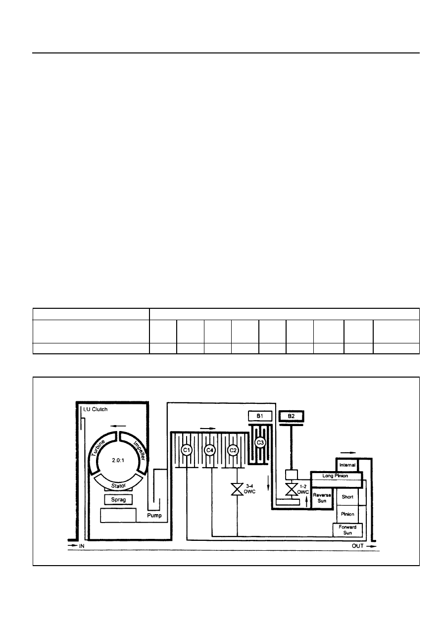
POWER FLOW - REVERSE
In Reverse, transmission drive is via the input shaft and the forward clutch cylinder to the hub of the C3 clutch. The
elements of the transmission function as follows :
!
The C3 clutch is engaged and drives the reverse sun gear in a clock-wise direction.
!
The B2 band is engaged and holds the planetary gear carrier stationary causing the long pinion to rotate anti-
clockwise about its axis on the pinion shaft.
!
The long pinion drives the internal ring fear in the same direction.
!
The internal ring being splined to the output shaft drives it in an anti-clockwise or reverse direction.
Control
To maintain this arrangement in the steady state
solenoids and valves are activated as follows:
!
Solenoids S1 and S2 are switched off.
!
Line pressure is directed through the reverse lockout valve to both the inner and outer apply areas of the rear
servo piston for B2 band application.
!
Line pressure feeds the reverse oil circuit via the manual valve.
!
Reverse oil is routed from the manual valve to the C3 clutch.
!
Reverse oil is also applied to the spring end of the primary regulator valve to assist the spring and to boost the
line pressure value.
!
All other clutch and band apply circuits are open to exhaust.
Refer to figure 5.2 and table 5.3
Table 5.3 - Engaged Elements - Reverse
Gear State
Reverse
C1
-
C2
-
C3
X
C4
-
B1
-
B2
X
1-2
OWC
-
3-4
OWC
-
LU
CLUTCH
-
ELEMENTS ENGAGED

5A-50 AUTOMATIC TRANSMISSION
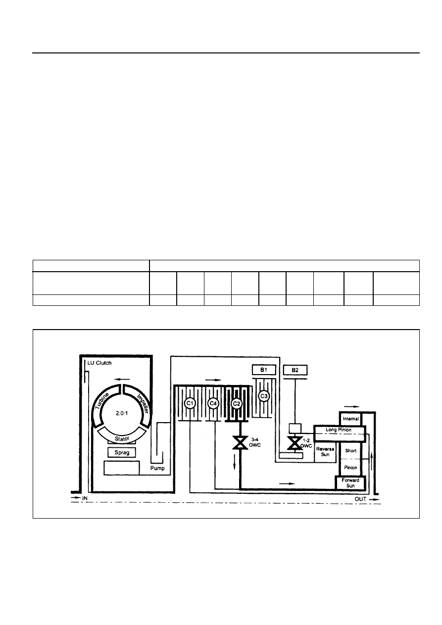
POWER FLOW - MANUAL 1
In Manual 1, transmission drive is via the input shaft
to the forward clutch cylinder. The elements of the
transmission function as follows :
!
The C2 clutch is engaged to drive the forward sun gear, via the 3-4 OWC.
!
The B2 band is engaged to hold the planetary gear carrier stationary.
!
The forward sun gear drives the short pinion anti-clockwise.
!
The short pinion drives the long pinion clockwise.
!
The long pinion rotating about its axis drives the internal ring gear and the output shaft in a clockwise or
forward direction.
!
The C4 clutch provides engine braking through the 3-4 OWC on overrun.
Control
To maintain this arrangement in the steady state solenoids and valves are activated as follows:
!
Solenoids S1 and S2 are switched ON.
!
The 1-2,2-3, and 34 shift valves are held in their first gear positions by line 500 pressure.
!
Drive (line pressure) oil from the manual valve engages the C2 clutch.
!
Lo-1st (line pressure) oil is routed through the 1-2 shift valve to the C4 clutch, and to the inner apply area of
the rear servo piston for B2 band application.
Refer to figure 5.3 and table 5.4.
Table 5.4 - Engaged Elements - Manual 1
Gear State
Manual 1
C1
-
C2
X
C3
-
C4
X
B1
-
B2
X
1-2
OWC
-
3-4
OWC
X
LU
CLUTCH
-
ELEMENTS ENGAGED
AUTOMATIC TRANSMISSION 5A-51
POWER FLOW - DRIVE 1
In Drive 1, transmission drive is via the input shaft to the forward clutch cylinder. The elements of the transmission
function as follows :
!
The C2 clutch is engaged to drive the forward sun gear.
!
The forward sun gear drives the short pinion anti-clockwise.
!
The short pinion drives the long pinion clockwise.
!
The 1-2 OWC prevents the planetary gear carrier from rotating under reaction force and the long pinion
rotates on its axis driving the internal ring gear and output shaft in a clockwise or forward direction.
!
There is no engine braking on overrun.
Control
To maintain this arrangement in the steady state solenoids and valves are activated as follows:
!
Solenoids S1 and S2 are switched On.
!
The 1-2, 2-3, and 3-4 shift valves are held in their first gear positions by line 500 pressure.
!
Drive (line pressure) oil from the manual valve engages the C2 clutch.
Refer to figure 5.4 and table 5.5
Table 5.5 - Engaged Elements - Drive 1
Gear State
Drive 1
C1
-
C2
X
C3
-
C4
-
B1
-
B2
-
1-2
OWC
X
3-4
OWC
X
LU
CLUTCH
-
ELEMENTS ENGAGED
5A-52 AUTOMATIC TRANSMISSION
POWER FLOW - DRIVE 2 AND MANUAL 2
In Drive 2 and Manual 2, transmission drive is via the input shaft and forward clutch cylinder. The elements of the
transmission function as follows :
!
The C2 clutch is applied to drive the forward sun gear.
!
The forward sun gear drives the short pinion anti-clockwise.
!
The short pinion drives the long pinion clockwise.
!
The B1 band is applied holding the reverse sun gear stationary therefore the long pinion ‘walks’ around the
reverse sun gear taking the internal ring gear and output shaft with it in a clockwise or forward direction.
!
The C4 clutch is applied to bypass the 3-4 OWC and provide engine braking on overrun.
Control
To maintain this arrangement in the steady state solenoids and valves are activated as follows: Solenoid S1 is
switched Off. S2 is switched On.
!
Solonoid S1 is switched Off. S2 is switched On.
!
Drive (line pressure) oil from the manual valve engages the C2 clutch.
!
When S1 switches off , S1 oil pressure, which is derived from line 500 pressure, moves the 3-4 shift valve to
the left. At the same time S1 oil is directed to the 1-2 shift valve which moves the valve to the second gear
position.
!
2nd oil (line pressure) from the 1-2 shift valve is directed to the band apply regulator valve, and to the 2-3 shift
valve.
!
The band apply regulator valve supplies 2nd oil (regulated to line pressure multiplied by the valve ratio) to the
band apply feed (BAF) circuit.
!
Band apply feed oil is directed to:
- The outer apply area of the front servo
- The 1-2 shift valve to provide an exhaust port when the transmission is shifted to first gear
- The 3-4 shift valve for use when the transmission is shifted into fourth gear
!
Drive (line pressure) is routed through the 3-4 shift valve to apply the C4 clutch.
Refer to figure 5.5 and table 5.6.
Table 5.6 - Engaged Elements - Drive 2 and Manual 2
Gear State
Drive 2 and Manual 2
C1
-
C2
X
C3
-
C4
X
B1
X
B2
-
1-2
OWC
-
3-4
OWC
X
LU
CLUTCH
-
ELEMENTS ENGAGED
Нет комментариевНе стесняйтесь поделиться с нами вашим ценным мнением.
Текст