SsangYong Musso. Manual — part 344
M161 ENGINE CONTROLS 1F2-55
Removal & Installation Procedure
1. Remove the O-ring.
Check for damage and replace it if necessary.
2. Remove the injector bracket from the injector.
Installation Notice
Exactly seat the anti-twist lock into the square groove in
injector.
3. Separate the injector from the fuel distributor.
Inspection & Maintenance
Inspection of the Injector operation and spray pattern
1. Connect the contact box to the ECU.
2. Connect the shop made test plug to the injector and place
it into the tank.
3. Position the ignition switch to ON.
4. Connect the pin 63(+) and 69(-) of the contact box with a
test cable.
5. Check the injector spray pattern.
Notice
Replace the injector if the injector spray pattern is abnormal
or the fuel doesn't inject.
Injector Resistance Inspection
1. Remove the injector connector.
2. Measure the injector coil resistance using a resistance
tester.
Notice
Replace the injector if the measured values is out of the
specified values. Check the connector and wire connection
between the ECU and the injector if the measured values
are normal.
Specified Value
14 - 17
Ω
1F2-56 M161 ENGINE CONTROLS
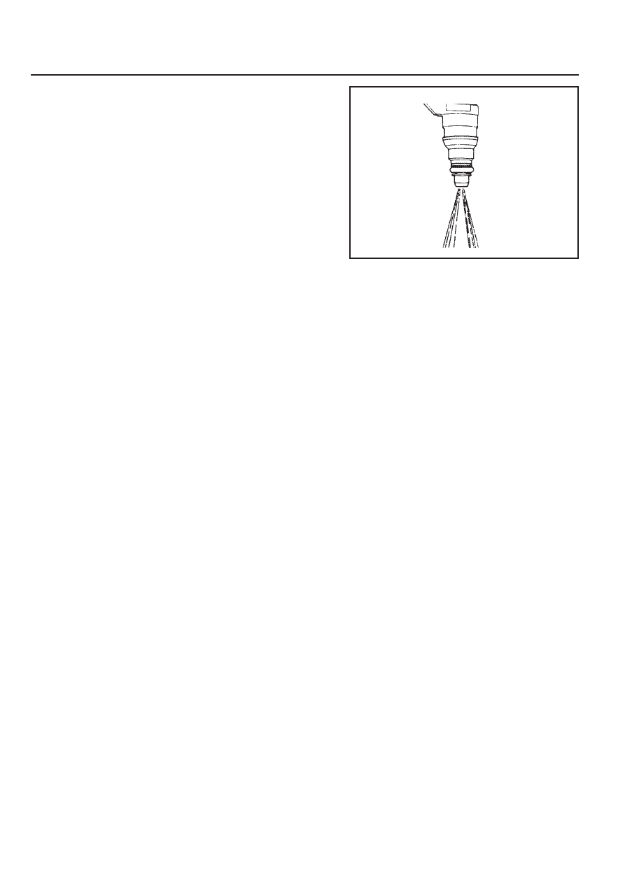
The Injector Spray Pattern Check
1. Connect the test box (129 589 00 21 00) to the ECU.
2. Disconnect the connector from connector.
3. Disconnect the fuel distributor and injector with a unit from
engine without removing the fuel supply and return line.
Notice
Prepare the beaker for taking the poping fuel.
4. Connect either end of shop made cable to the injector.
5. Connect the other end of shop made cable to the (+:63)
and (-:69) terminal of the test box.
6. Turn the ignition switch to "ON" position.
7. Check the injector for normal spray pattern as shown in the
figure. Check injector for leaks or later drops.
Notice
Refer to fuel injector test of engine diagnosis in this section
for detailed information.
M161 ENGINE CONTROLS 1F2-57
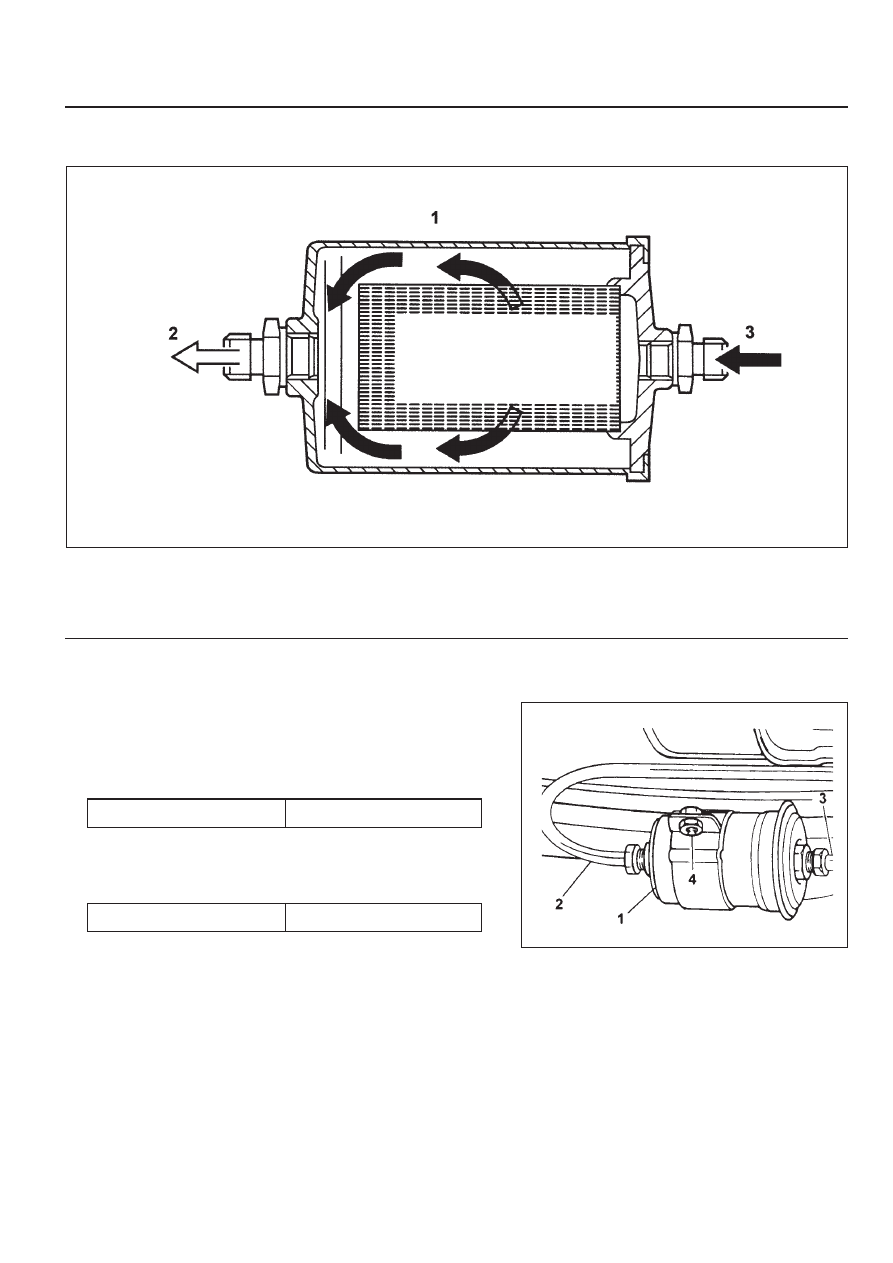
FUEL FILTER
1 Fuel Filter
2 Outlet
Removal & Installation Procedure
1. Open the fuel tank cap and remove the fuel tank pressure.
2. Remove the fuel out (2) and in (3).
Installation Notice
Notice
Place the fuel pump pad. There may be a corrosion due to
the contact between the fuel filter and the bracket.
4. Check for leaks by operating the engine.
Notice
Installation should follow the removal procedure in the
reverse order.
3. Remove the mounting bracket bolt (4) and remove the fuel
filter (1).
Installation Notice
3 Inlet
Tightening Torque
25 - 30 Nm
Tightening Torque
4 - 8 Nm
1F2-58 M161 ENGINE CONTROLS
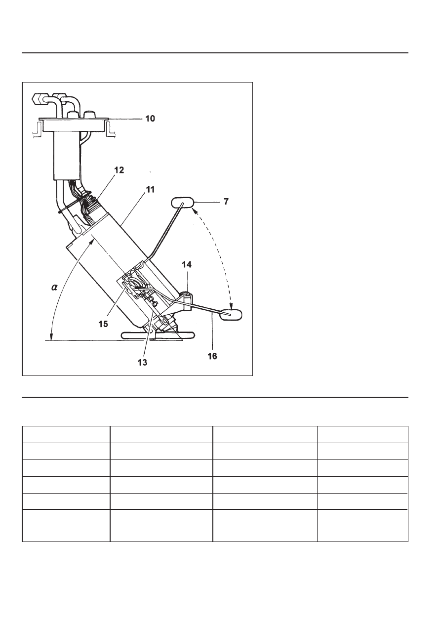
FUEL PUMP
Requirements for Fuel Pump
Item
Specified Value
Item
Specified Value
System pressure
3.8 bar
Minimum delivery at 8V
30 Litre/Hr
Maximum pressure
8.5 bar (12 V)
Minimum amount
of fuel supply
114 Liter/Hr (12 V, 3.8 bar, -
30 ~ +70°C)
Minimum pressure
5.0 bar (12 V)
Maximum allowable current
7.5 A
Nominal voltage
12 V
Ambient temperature
-30 ~ +70°C
1 Reservoir Tank
2 Fuel Sensor (float/arm)
3 Resistance
4 Wiring Connector
5 Fuel Supply Pipe
7 Float
10 Flange and Harness Assembly
11 Fuel Pump
12 Spring
13 Thermister Housing
14 Thermister
15 Resistor Card and Wiper
16 Float Arm
Operating voltage
8 V
Maximum amount
of fuel supply
165 Liter/Hr (12V, 3.8 bar,
-30 ~ +70°C)
Нет комментариевНе стесняйтесь поделиться с нами вашим ценным мнением.
Текст