SsangYong Musso. Manual — part 520
TRANSFER CASE (TOD) 5D2-27
Defect in speed sensor : fault code 1731, 1732,
1733, 1734, 1735,1736
!
Phenomenon
1. Upon diagnosis by SCANNER, it displays on fault code
1731, 1732, 1733, 1734, 1735 and 1736.
2. “4WD CHECK” lamp illuminates continuously when
ignition “ON”.
!
Cause
1. Defect of speed sensor (front, rear).
2. Defect of power supply.
4.75-5.25Vdc
Yes
No
D1
Yes
No
D2
Yes
Yes
Yes
No
D3
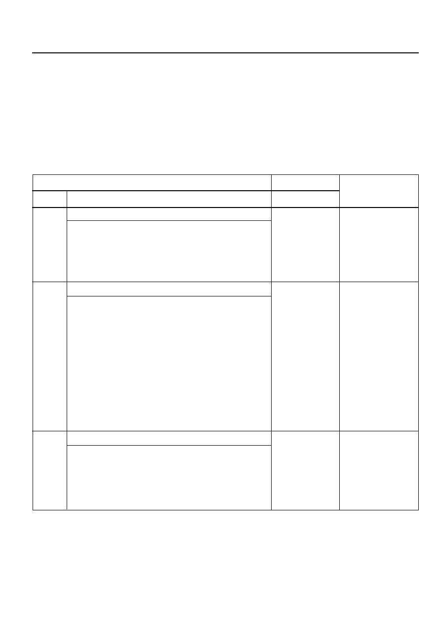
Test Stage / Contents
Result
Stage
Test Contents and Procedure
Specified Value
/Yes/No
Countermeasure
Check power supply of speed sensor.
1. Ignition “ON” or driving mode
2. Measure supply voltage between pin 16 (+) and 13 (-) in
TOD control unit connector using digital multi-tester.
- Specified value
- Measured value is within specified range ?
Check connection status of connector.
1. Check connection status of speed sensor/clutch coil
connector and TOD control unit connector.
- Does it connect correctly ?
2. In case of bad connection, connect it correctly then
perform the follows:
a. Delete the memorized fault code in control unit by
SCANNER.
b. Ignition “OFF”.
c. Ignition “ON”.
d. Diagnose by SCANNER.
- It does not display fault code.
- It displays one or more fault code among 1731 to
1736.
Check output wave of front and rear speed sensor.
1. Upon driving mode.
2. Check output wave of each speed sensor by SCANNER.
3. Is it normal on output wave ?
Perform D3 stage
Perform D2 stage
Perform D3 stage
Perform D2-2 stage
Normal system
Perform D3 stage
Perform D4 stage
Replace speed
sensor then
perform D2-2 stage

5D2-28 TRANSFER CASE (TOD)
Yes
No
D4
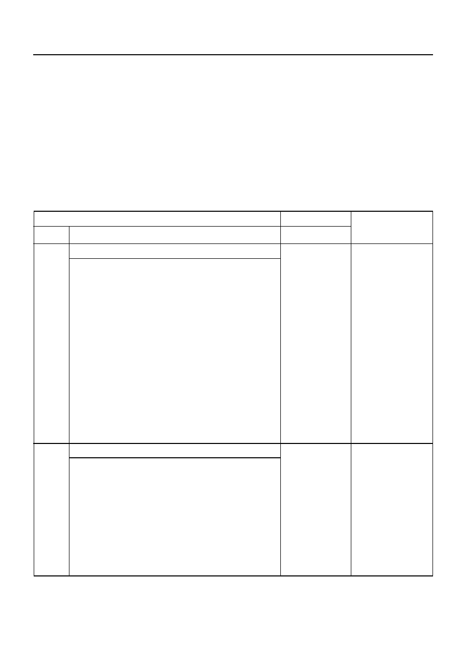
Test Stage / Contents
Result
Stage
Test Contents and Procedure
Specified Value
/Yes/No
Countermeasure
Check output voltage of front and rear speed sensor.
1. Upon driving mode
2. Measure output voltage of front and rear speed sensor
by multi-tester. Check voltage whether it varies within
specified range.
- Specified value
• Front speed sensor
: Pin 11(+), 13(-) in TOD control unit connector
• Rear speed sensor
: Pin 29(+), 13(-) in TOD control unit connector
- Measure value is within specified range ?
Check function of
control unit.
It necessary,
replace then delete
fault codes and re-
diagnose .
Perform D5 stage
Yes
No
D5
Check short/open in cable.
1. Ignition"OFF"
2. Disconnect TOD control unit connector
3. Make a test for open circuit between pin 11 and 13, 16
and 13, 29 and 13 in wiring connector by multi-tester.
- Is there a resistance of "
∞
" ?
4. Make a test for short between pin 11 and ground 13
and ground, 29 and ground by multi-tester.
- Is there a resistance of "
∞ Ω
" ?
Repair wire Perform
D5-4 stge
Yes
No
Wiring short, repair
Perform D3 stage,
then delete fault
codes with
rediagnosis
TRANSFER CASE (TOD) 5D2-29
Shift motor malfunction : Fault code ® 1741,
1742, 1743
!
Phenomenon
1. When change the 4H/4L switch from 4H to 4L, ‘4L’
indicator lamp turn off after blinking for a time and then
‘4WD CHECK’ indicator lamp turn on.
2. Fault codes display by diagnosis of SCAN-100 : 1741,
1742, 1743
3. The shifting operation is not occurred when 4H / 4L switch,
is operating.
!
Cause
Defect in shift motor, improper voltage provided, incorrect
connection in connector, short of wiring.
11-14 V
(Battery voltage)
Yes
No
E1
11-14 V
(Battery voltage)
Yes
No
Yes
No
E2
Yes
No
Test Stage / Contents
Result
Stage
Test Contents and Procedure
Specified Value
/Yes/No
Countermeasure
Check the input voltage of shift motor.
1. Turn the ignition switch to “ON” position.
2. Measure the Hi/Low voltage of motor which is located
between No.1/No.14 and No.2/No.15 connector of TOD
control unit with digital Multi-tester or which is located
between No.G connector and body after detaching T/C
motor connector.
- The specified value (When operates 4H/4L switch)
- Measured value is within specified range ?
3. Measure the Hi/Low voltage of motor which is located
between No.2/No.5 and No.1/No.14 connector or which
is located No.B connector and body after detaching T/C
motor connector
- The specified value (When operates 4H/4L switch)
- Measured value is within specified range ?
Check the fault condition of the relevant connector.
1. Check the installation condition of TOD control unit 30pin
connector and T/C shift motor connector.
- Is it installed properly ?
2. If the connector installation is improper, install properly
and then perform follows :
a. Delete the fault code of control unit by scan scope
b. Turn off the ignition switch
c. Turn on the ignition switch
d. Re-diagnosis of system
It displays one or more fault code among 1741 to 1743.
Perform E1-3 stage
Perform E2 stage
Perform E4 stage
Perform E2 stage
Perform E3 stage
Perform E2-2 stage
Perform E3 stage
Normal system

5D2-30 TRANSFER CASE (TOD)
Yes
No
Yes
No
Yes
No
E3
Yes
No
E4
Yes
No
E5
Test Stage / Contents
Result
Stage
Test Contents and Procedure
Specified Value
/Yes/No
Countermeasure
Check the wiring of shift motor whether it is shorted or not.
1. Turn off the ignition switch.
2. Detach the 30pin connector from TOD control unit
3. Perform short test between the wiring connector No.1/
No.14 and No.2/No.5.
- Is there resistance of 0
Ω
?
4. Perform the short test between No.1/No.14 Connector
and body, No2/No.15 connector and body.
- Is there resistance of 0
Ω
?
5. Execute E1 stage to check whether wiring is shorted
between Hi-Low motor and LOW-HI motor.
- Is the provided voltage proper ?
Check the resistance of shift motor
1. Turn off the ignition switch.
2. Measure the resistance between No.1/No.14 and No.2/
No.15 connector after detaching 30pin connector of TOD
control unit Or, check the resistance between No.G and
No.B after detaching motor connector of T/C side.
- Specified value
- Measured value is within specified range ?
Execute the test after detaching shift motor, when the fault
is not solved after executing E1~E4 stage.
1. Detach the motor connector from T/C.
2. Remove the shift motor.
3. Connect motor connector with the removed shift motor.
4. Operate the 4H/4L switch.
- Does motor rotate ?
Hi-Low motor and
Lo-Hi wiring are
shorted each other.
Repair or replace.
Perform E3-4 stage.
Related wiring is
shorted with ground.
Repair or replace.
Perform E3-5 stage.
Perform E4 stage.
Wiring is shorted.
Repair or replace.
The defective T/C or
perform E5 stage.
Replace the shift
motor.
Check and fix due to
the defective T/C
ass’y.
Replace the motor
or delete fault code
and rediagnosis
system.
Нет комментариевНе стесняйтесь поделиться с нами вашим ценным мнением.
Текст