SsangYong Musso. Manual — part 488
AUTOMATIC TRANSMISSION 5A-129
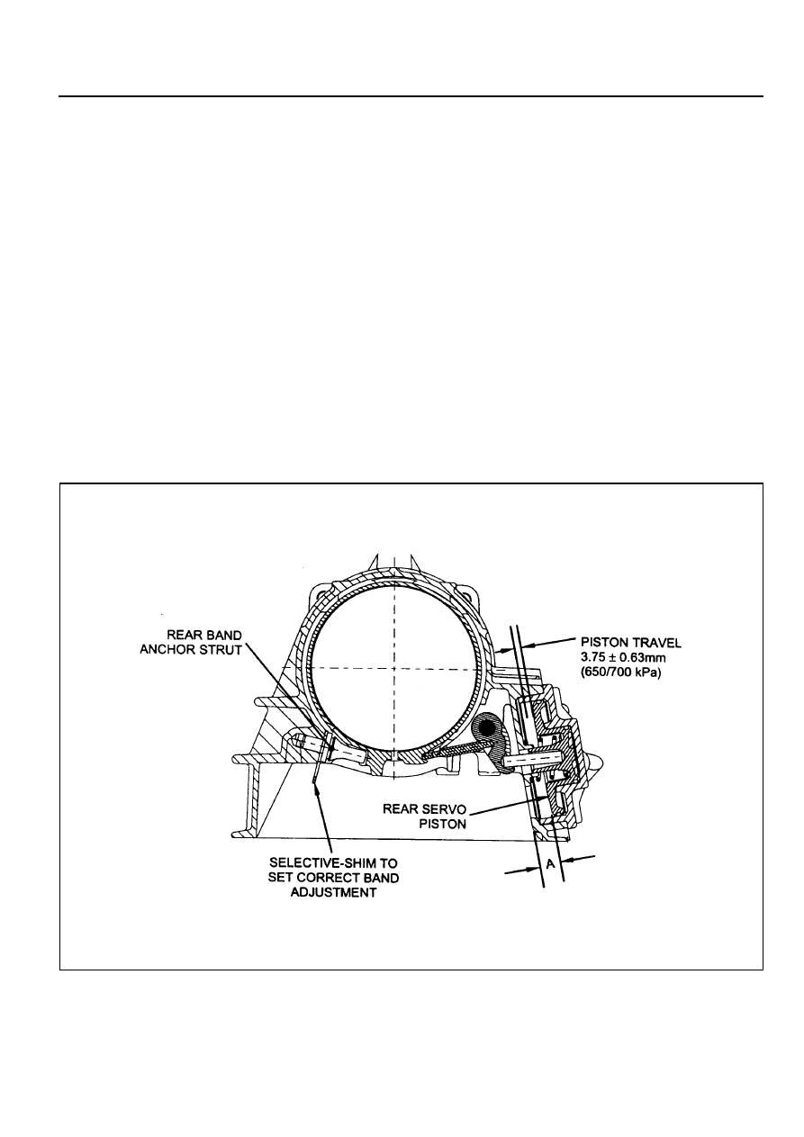
Figure 8.68 - Rear Band Settings
Rear Band Setting Procedure
To set the rear band, proceed as follows.
1. Measure distance ‘A’ from the rear servo piston to the inner face of the transmission case using vernier calipers.
Refer to figure 8.68.
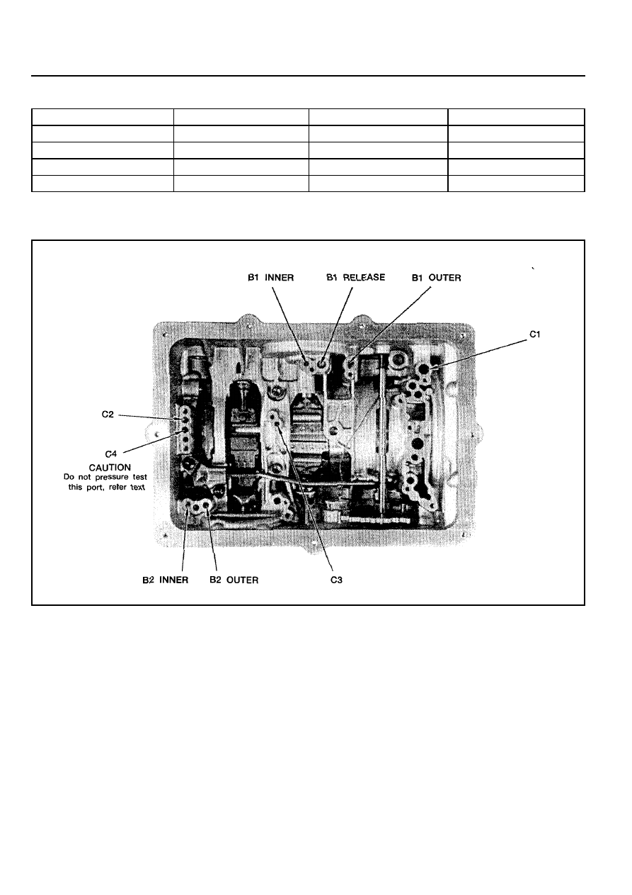
a. Apply air at 650/700 kPa to the rear servo apply area (B2 outer). Refer to figure 8.67.
b. Measure the travel of the piston, subtract 3.75 mm and divide the remainder by 2.5 to find shim size.
c. Release the air.
Notice
A minimum of one shim is required at all times - minimum shim size is 1 mm. The thickness of available shims
are listed in table 8.2.
2. Fit the selected shim(s) to the shank of the anchor strut as follows.
a. Inspect the shim(s) for damage, wear or corrosion and replace as necessary. The shim(s) are to be installed
between the case abutment face and the anchor strut flange. Refer to figure 8.68.
c. The shim(s) are to be fitted by hand and under no circumstances to be hammered or forced.
d. The shim(5) are to be pressed on by hand until an audible click is heard. The click indicates that the shim is
clipped home correctly.
3. Re-check that the piston travel is 3.75 mm
±
0.625 mm.
5A-130 AUTOMATIC TRANSMISSION
Table 8.2 - Thickness of Available Shims
Thickness
0.95/1.05
1.15/1.25
1.44/1.56
1.73/1.87
Part Number
0574-037017
0574-037018
0574-037019
0574-037020
Thickness
1.93/2.07
2.12/2.28
2.42/2.58
2.61/2.79
Part Number
0574-037021
0574-037022
0574-037023
0574-037024
Figure 8.68 - Thickness of Available Shims

Model
Type
Gear Ratio
Oil
Weight (Dry)
SECTION 5B
MANUAL TRANSMISSION
TABLE OF CONTENTS
Specifications . . . . . . . . . . . . . . . . . . . . . . . . 5B-1
General Specifications . . . . . . . . . . . . . . . . . . 5B-1
Fastener Tightening Specifications . . . . . . . . . 5B-2
External View . . . . . . . . . . . . . . . . . . . . . . . . 5B-3
Gear Train . . . . . . . . . . . . . . . . . . . . . . . . . . 5B-3
Power Flow . . . . . . . . . . . . . . . . . . . . . . . . . 5B-4
Diagnosis . . . . . . . . . . . . . . . . . . . . . . . . . . . 5B-5
Will not Shift (Control Lever Moves) . . . . . . . . 5B-5
Hard Shift or Control Lever Will not Move Into
Gear . . . . . . . . . . . . . . . . . . . . . . . . . . . . . . . . 5B-5
Gears Crash When Shifting . . . . . . . . . . . . . . 5B-5
Transmission Jumps Out . . . . . . . . . . . . . . . . . 5B-6
Transmission Locked in One Gear . . . . . . . . . 5B-6
Transmission Noise . . . . . . . . . . . . . . . . . . . . . 5B-6
Transmission Leakage . . . . . . . . . . . . . . . . . . 5B-7
Diagnosis Table . . . . . . . . . . . . . . . . . . . . . . . 5B-8
Component Locator . . . . . . . . . . . . . . . . . . . 5B-9
Maintenance and Repair . . . . . . . . . . . . . . 5B-11
On-Vehicle Service . . . . . . . . . . . . . . . . . . . . 5B-11
Shift Control Cable . . . . . . . . . . . . . . . . . . . . 5B-11
Transmission . . . . . . . . . . . . . . . . . . . . . . . . 5B-14
Unit Repair . . . . . . . . . . . . . . . . . . . . . . . . . 5B-17
Major Unit . . . . . . . . . . . . . . . . . . . . . . . . . . . 5B-17
Main Shaft . . . . . . . . . . . . . . . . . . . . . . . . . . 5B-27
Input Shaft . . . . . . . . . . . . . . . . . . . . . . . . . . 5B-32
Counter Shaft . . . . . . . . . . . . . . . . . . . . . . . . 5B-34
Extension Housing . . . . . . . . . . . . . . . . . . . . 5B-35
Shift Cover . . . . . . . . . . . . . . . . . . . . . . . . . . 5B-36
Inspection of Components . . . . . . . . . . . . . . 5B-40
Pre-Installation Checks . . . . . . . . . . . . . . . . . 5B-45
SPECIFICATIONS
GENERAL SPECIFICATIONS
Application
Description
T5WC
Floor Change
3.97 : 1
2.34 : 1
1.46 : 1
1.00 : 1
0.85 :1
3.71 : 1
ATF DEXRON II / III
3.4 L
Check : Every 15,000km, Replace : Every 50,000km
33kg
1st
2nd
3rd
4th
5th
Reverse
Specification
Capacity(litre)
Change Interval
Notice
Add LUBRIZOL (280cc) in oil after overhauling.

5B-2 MANUAL TRANSMISSION
FASTENER TIGHTENING SPECIFICATIONS
Application
Transmission
Oil Filler Plug
Transmission Mounting Bolt (Housing)
Oil Drain Plug
Front Propeller Shaft (T/C)
Rear Propeller Shaft (T/C)
Cross Member Bolt (Center)
Cross Member Bolt (Side)
Control Cable
Shift Lever Bolt
N
!
!
!
!
!
m
25
77 - 87
25
81 - 89
70 - 90
21 - 35
62 - 93
20 - 30
Нет комментариевНе стесняйтесь поделиться с нами вашим ценным мнением.
Текст