SsangYong Musso. Manual — part 341

M161 ENGINE CONTROLS 1F2-43
Pin No.
Abbreiation
Description
-
-
-
-
-
-
-
-
Crankshaft sensor ground
Crankshaft sensor signal
-
-
-
Camshaft sensor ground
Hot film air mass ground
Camshaft sensor signal
-
Hot film air mass supply
-
-
-
E-GAS potentiometer supply
-
-
-
-
Knock sensor 1 ground
Knock sensor 1 signal
-
-
91
92
93
94
95
96
97
98
99
100
101
102
103
104
105
106
107
108
109
110
111
112
113
114
115
116
117
118
119
120
-
-
-
-
-
-
-
-
KW-
KW+
-
-
-
NOWE-
GND
NOWE+
-
V-REF.HFM
-
-
-
V-REF.DK
-
-
-
-
GND
KS1
-
-
-
-
-
-
-
-
-
-
z
z
-
-
-
z
z
z
-
z
-
-
-
z
-
-
-
-
z
z
-
-
-
-
-
-
-
-
-
-
z
z
-
-
-
z
z
z
-
z
-
-
-
z
-
-
-
-
z
z
-
-
E23 ENG,
4speed A/T
E23 ENG,
5speed A/T
-
-
-
-
-
-
-
-
z
z
-
-
-
z
z
z
-
z
-
-
-
z
-
-
-
-
z
z
-
-
E23 ENG,
4speed A/T
1F2-44 M161 ENGINE CONTROLS
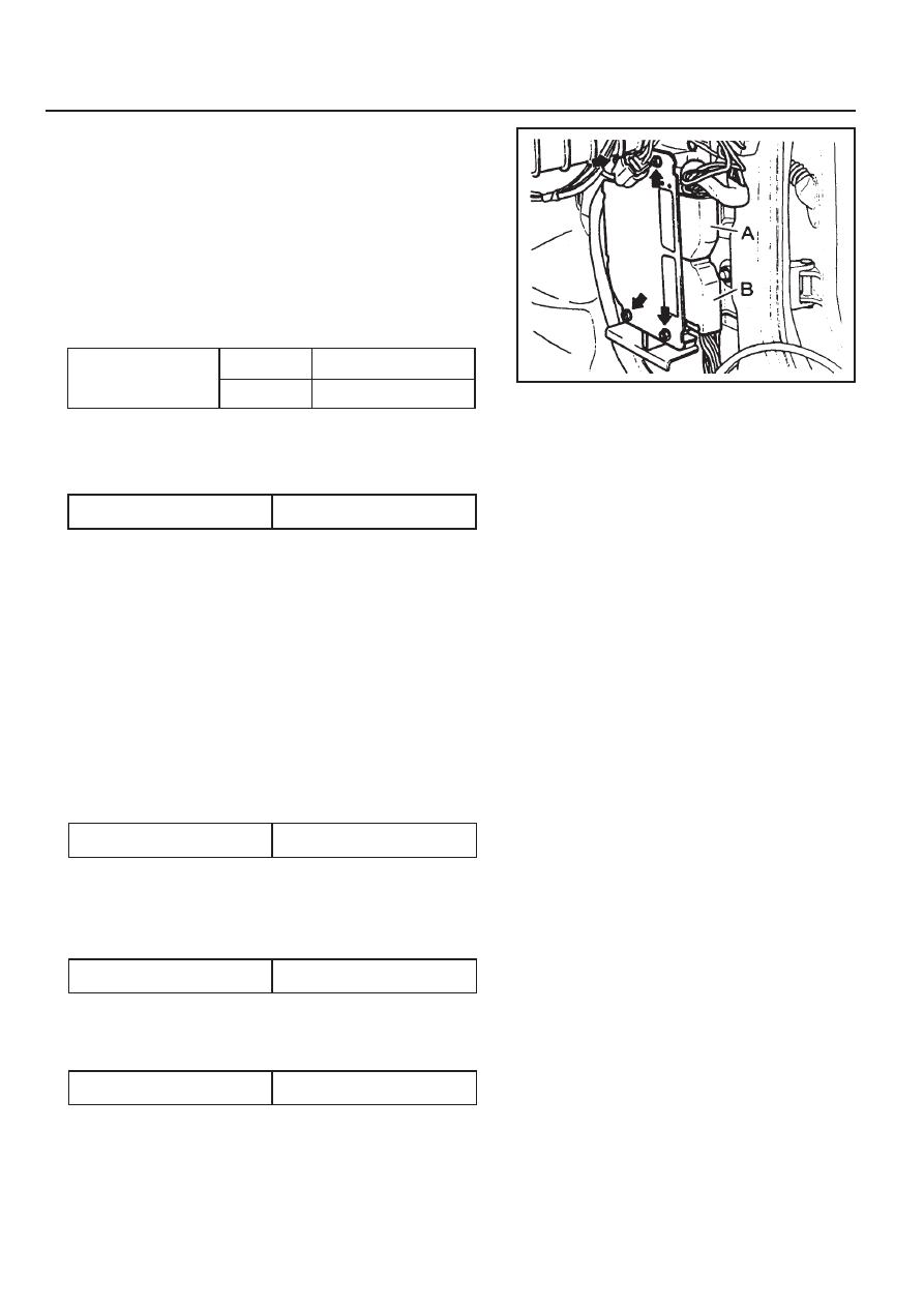
Removal & Installation Procedure
•••••
When removing the ECU only
1. Turn the ignition switch to "OFF" position.
2. Disconnect the negative battery cable.
3. Disconnect the couplings from ECU.
4. Unscrew the left and right bolt (3) on bolt (1) and auxiliarly
bracket and remove the auxiliarly bracket from the bracket
assembly (2).
Installation Notice
5. Unscrew the four bolts (5) and disconnect the ECU (6) from
the bracket assenbly.
Installation Notice
6. Installation should follow the removal procedure in the
reverse order.
Tightening Torque
6 - 8 Nm
5 - 7 Nm
(1)
(3)
Tightening Torque
5 - 7 Nm
8. Unscrew the bolts (5) and disconnect the ECU (6) from the
bracket assenbly.
Installation Notice
•••••
When Removing the ECU with ABS or ABS/ASR Unit
1. Turn the ignition switch to "OFF" position.
2. Disconnect the negative battery cable.
3. Disconnect the couplings from ECU.
4. Disconnect the coupling from ABS or ABS/ASR unit.
5. Unscrew the bolt (1) and the left and right flange nuts.
6. Remove the ECU with ABS or ABS/ASR unit assembly.
7. Unscrew the left and right bolt (3) on the auxiliary bracket
and remove the auxiliary bracket from the bracket assembly.
Installation Notice
Tightening Torque
6 - 8 Nm
Tightening Torque
5 - 7 Nm
Tightening Torque
5 - 7 Nm
9. Installation should follow the removal procedure in the
reverse order.
M161 ENGINE CONTROLS 1F2-45
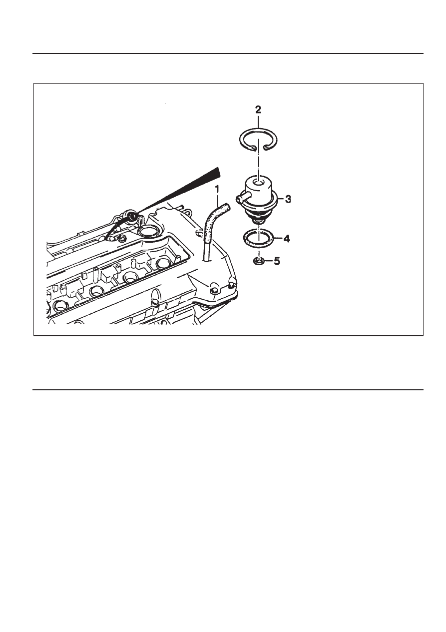
1 Vacuum Hose
2 Circlip
3 Fuel Pressure Regulator
FUEL PRESSURE REGULATOR
4 O-ring . . . . . . . . . . . . . . replace
5 O-ring . . . . . . . . . . . . . . replace
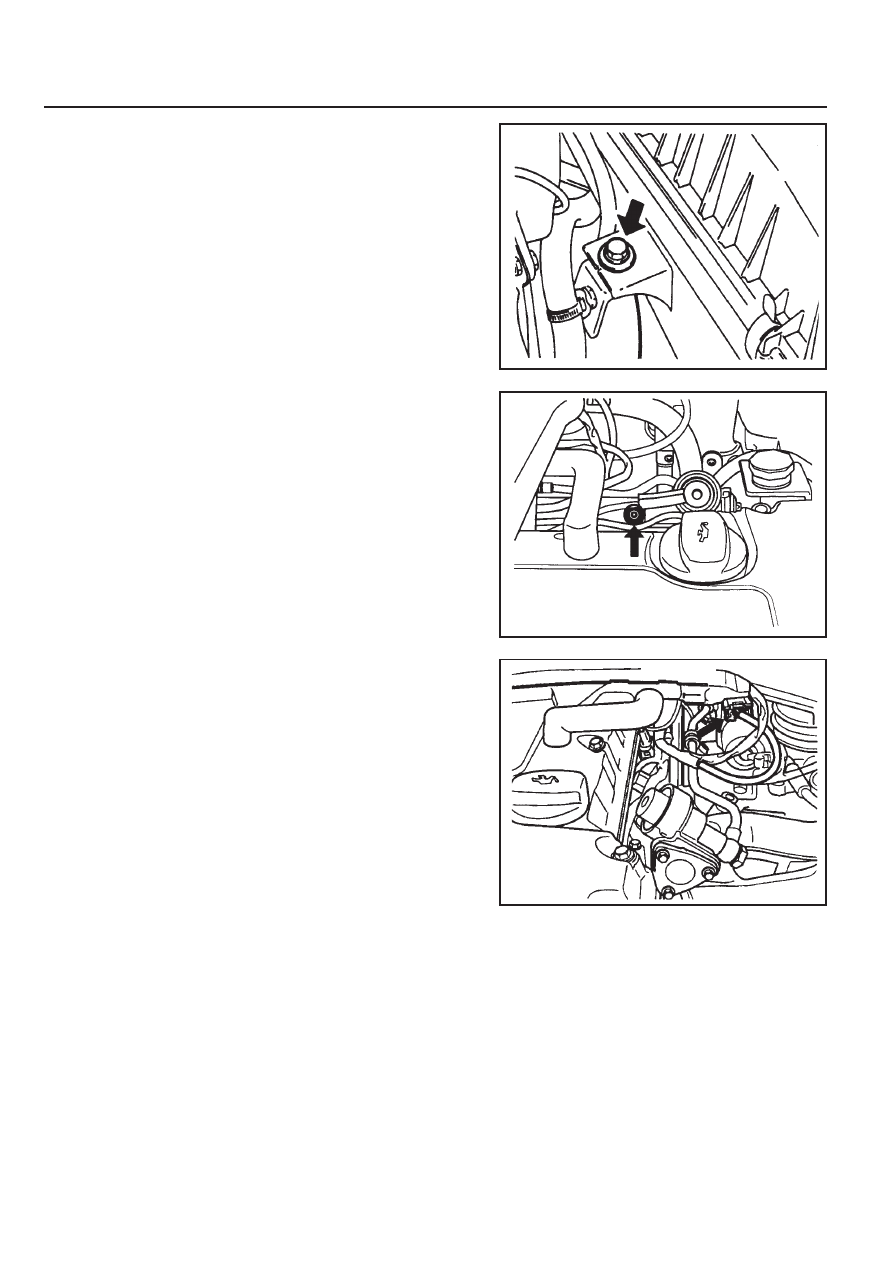
1F2-46 M161 ENGINE CONTROLS
3. Disconnect the vacuum hose.
4. Disconnect the circlip and remove the fuel pressure
regulator.
5. Apply the oil to O-ring lightly and then replace it.
6. Installation should follow the removal procedure in the
reverse order.
7. Check for fuel pressure and internal leaks by operating the
engine.
2. Discharge the pressure in fuel supply system by pressing
the service valve.
Removal & Installation Procedure
1. Remove the fuel pressure test connector.
Нет комментариевНе стесняйтесь поделиться с нами вашим ценным мнением.
Текст