SsangYong Musso. Manual — part 451
ANTILOCK BRAKE SYSTEM 4F-11
ABS, ABS/ABD 5.0
Initializing
1. Set the ignition switch n “ON” position.
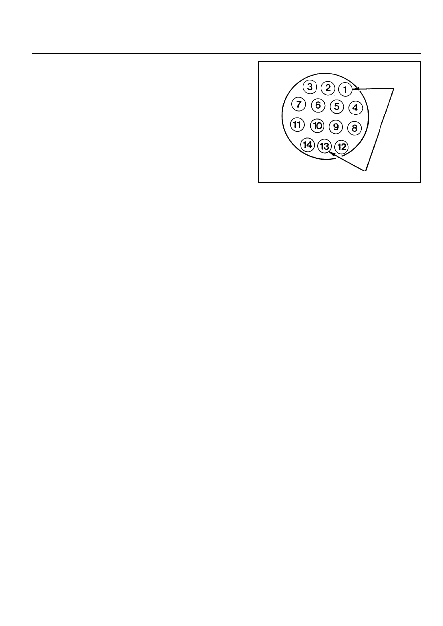
2. Connect the No.1 terminal (Ground) and the No.13 (ABS)
from diagnosis socket located in E/G room by use of service
connector for 3 - 4 seconds and initialize the flash code.
Notice
Be careful not to connect over 5 seconds.
3. ABS indicator warning light continuously comes on until the
ignition switch is “OFF”.
Dignosis Table
1. When the system is normal
!
One pulse (normal code 01) indicates.
2. When the system is abnormal
!
One pulse (defect code) indicates.
Notice
Repeat the initializing procedure when checking the
defect code Defect code is indicated once for 1 sec (light
on : 0.75 sec, light off : 0.25 sec).
Removal the Defect Code
1. Repair the defect code and remove the memorized defect
code in the ECU.
2. Connect the No. 13 terminal (ABS) from diagnosis socket
and No. 1 terminal (ground) for over 5 seconds.
3. Set the ignition switch in the “OFF” position.
Notice
!
Defect code will be memorized in ECU unless the defect
code is not removed.
!
Repeat the initializing procedure and check the other
defects.
4F-12 ANTILOCK BRAKE SYSTEM
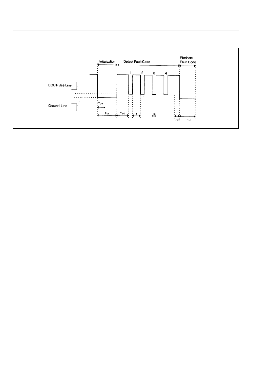
Diagnosis the Flash Code
[ex]
!
Time differences of nromal code 01 : TW1<T<Te<TW2
!
Time differences of fault code 15 : TW1<T<Te<TW2
Time Characteristics
1. Initialization
Tba < 5.0 sec.
Tba 1.8 - 2.2 sec.
2. Output of fault code
TW1 = 1.8 - 2.2 sec.
TW2 = 1.8 - 2.2 sec.
T = 0.75 sec., Te
≥
0.25 sec.
3. Elimination of fault code
Tb1 = 5.0 sec.

ANTILOCK BRAKE SYSTEM 4F-13
DEFECT CODES
Description
-
Replace the ECU
!
Check resistance of the wheel speed sensor :
1.280K
Ω
- 1.920K
Ω
!
Check wire for ground and open.
!
Replace the sensor.
!
Check resistance of the wheel speed sensor :
1.280K
Ω
- 1.920K
Ω
!
Check wire for ground and open.
!
Replace the sensor.
!
Check resistance of the wheel speed sensor :
1.280K
Ω
- 1.920K
Ω
!
Check wire for ground and open.
!
Replace the sensor.
!
Check resistance of the wheel speed sensor :
1.280K
Ω
- 1.920K
Ω
!
Check wire for ground and open.
!
Replace the sensor.
!
Check wire for ground and open.
!
Check connection of the wheel speed sensor connec-
tor and ECU side connector.
!
Measure air gap between wheel teeth and wheel speed
sensor and check installation of wheel tooth.
(Standard air gap : 0.35 - 1.60 mm)
!
Check output voltage of the sensor by rotating the
wheel 1/2 - 1 revolution per second and shaking sen-
sor wire.
-
When measured by multi - meter (AC) :
output voltage > 70 mV
-
When measured in oscilloscope :
output voltage
≥
120 mV/P-P
!
Replace the sensor.
!
Check wire for ground and open.
!
Check connection of the wheel speed sensor. con-
nector and ECU side connector.
!
Measure the air gap between wheel teeth and wheel
speed sensor and check installation of wheel tooth.
(Standard air gap : 0.35 - 1.60 mm)
!
Check output voltage of the sensor by rotating the
wheel 1/2 - 1 revolution per second and shaking sen-
sor wire.
Defect Code
01
02
03
04
05
06
07
08
Application
Normal
Defective ECU
Front/left Wheel Speed
Sensor (Wire)
Front/right Wheel Speed
Sensor (Wire)
Rear/left Wheel Speed
Sensor (Wire)
Rear/right Wheel Speed
Sensor (Wire)
Front/left Wheel Speed
Sensor (Signal)
Front/right Wheel Speed
Sensor (Signal)

4F-14 ANTILOCK BRAKE SYSTEM
Description
-
When measured by multi - meter (AC) :
output voltage > 70 mV
-
When measured in oscilloscope :
output voltage
≥
120 mV/P-P
!
Replace the sensor.
!
Check wire for ground and open.
!
Check connection of the wheel speed sensor con-
nector and ECU side connector.
(Standard air gap : 0.15 - 1.20 mm)
!
Check output voltage of the sensor by rotating the
wheel 1/2 - 1 revolution per second and shaking sen-
sor wire.
-
When measured by multi - meter (AC) :
output voltage > 70 mV
-
When measured in oscilloscope :
output voltage
≥
120 mV/P-P
!
Replace the sensor.
!
Check wire for ground and open.
!
Check connection of the wheel speed sensor con-
nector and ECU side connector.
!
Measure air gap between wheel teeth and wheel
speed sensor and check installation of wheel tooth.
(Standard air gap : 0.15 - 1.20 mm)
!
Check output voltage of the sensor by rotating the
wheel 1/2 - 1 revolution per second and shaking sen-
sor wire.
-
When measured by multi - meter (AC) :
output voltage > 70 mV
-
When measured in oscilloscope :
output voltage
≥
120 mV/P-P
!
Replace the sensor.
!
Check number of teeth on the wheel rotor and its
condition.
-
Number of teeth : 52
!
Check valve relay voltage.
!
Check connection of connector and terminals in the
ECU and hydraulic modulator.
!
Check ground.
!
Check terminals for open or short.
(When connector is removed)
!
Replace the hydraulic modulator.
Defect Code
09
10
11
12
Application
Rear/left Wheel Speed
Sensor (Signal)
Rear/right Wheel Speed
Sensor (Signal)
Wheel Rotor
Valve Relay
Нет комментариевНе стесняйтесь поделиться с нами вашим ценным мнением.
Текст