SsangYong Actyon Sports II. Manual — part 78
01-10
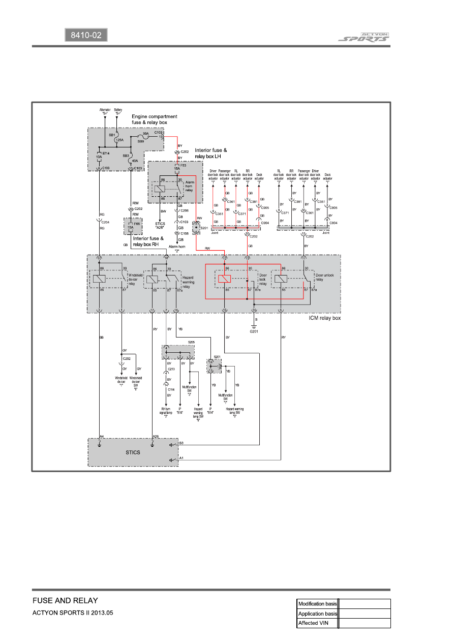
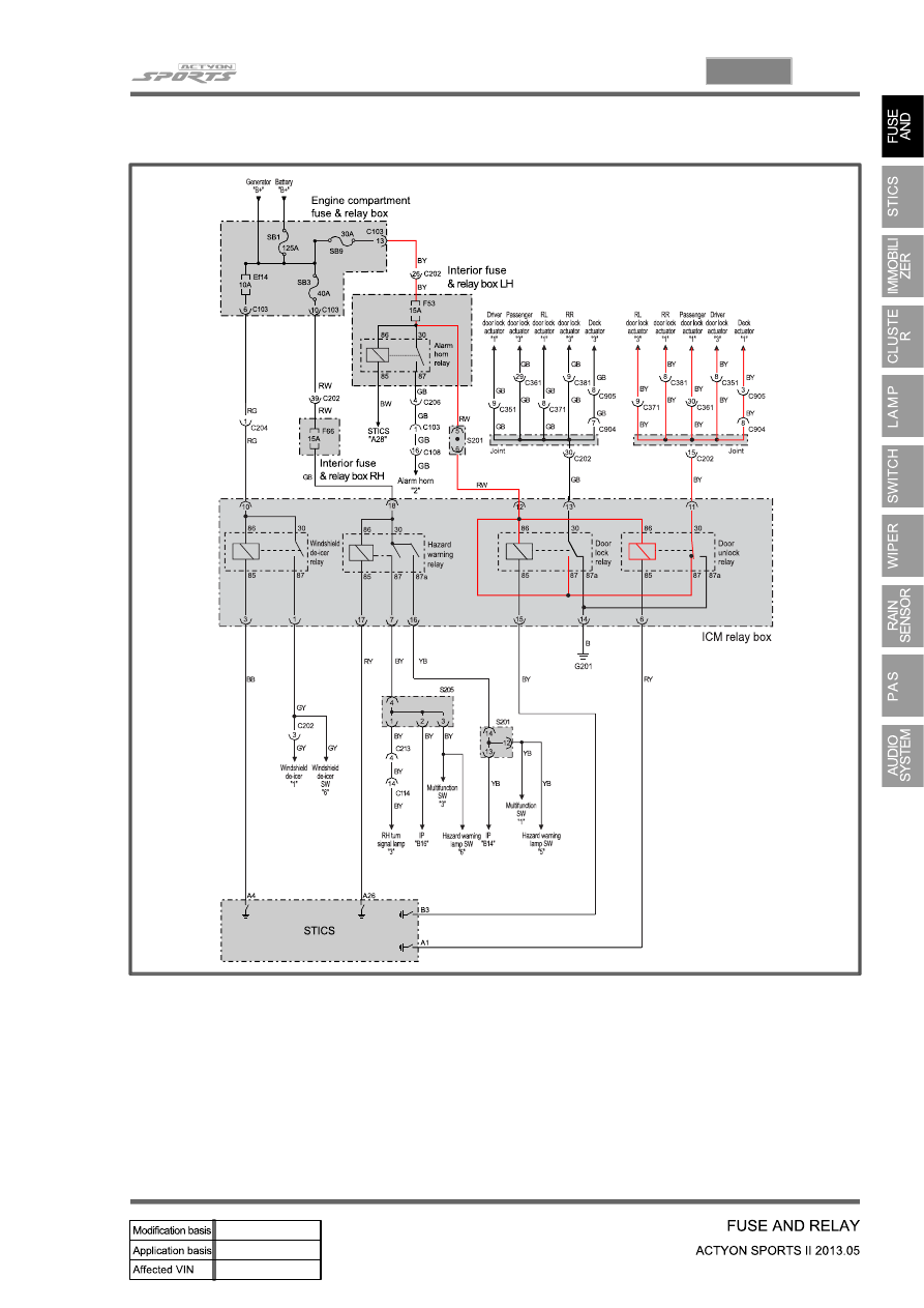
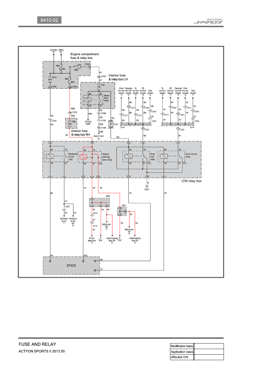
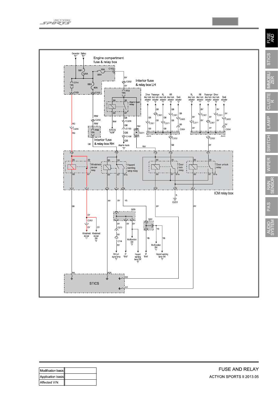
3) Operating Process by Power Supply of ICM Box
(1) Door lock relay
The power supplied through the No. F53 interior fuse on the left-hand of the engine compartment is on
standby on the No. 86 and 87 door lock relay terminals and No. 86 and 87 door unlock relay terminals
via the ICM No. 12 terminal. The STICS activates and/or controls the door lock relay connected to the
ICM No. 15 terminal using the STICS No. B3 terminal depending on the operating conditions. The
activated door lock relay supplies the No. 30 terminal with the B+ power, which is standby on the No. 87
terminal and supplies each door actuator with the B+ power.
The supplied power flows to the G201 ground connected to the ICM No. 14 terminal via the No. 30 and
87a door unlock relays for corresponding load.
01-11
8410-02
(2) Door unlock relay
The supply power is on standby in the same way as the door lock relay, and the STICS activates and/or
controls the door unlock relay connected to the ICM No. 6 terminal using the STICS No. A1 terminal
depending on the operating conditions. The activated door unlock relay supplies the No. 30 terminal with
the B+ power, which is standby on the No. 87 terminal and supplies each door actuator with the B+
power.
The supplied power flows to the G201 ground connected to the ICM No. 14 terminal via the No. 30 and
87a door lock relays for corresponding load.
01-12
(3) Turn signal lamp (Hazard warning lamp operation)
The B+ power supplied through the No. F66 interior fuse on the right-hand of the engine compartment is
on standby on the No. 30 and 86 hazard warning lamp relay terminals via the ICM No. 18 terminal.
The STICS activates and/or controls the hazard warning lamp relay using the No. A26 terminal
depending on the operating conditions. The activated relay supplies the No. 87 and 87a terminals with
the power, which is on standby on the No. 30 hazard warning lamp relay terminal.
The supplied power flows to the corresponding circuit via the No. 7 and 16 ICM terminals.
01-13
8410-02
(4) Windshield de-icer operation
The B+ power supplied through the No. Ef14 fuse and relay box in the engine compartment is on
standby on the No. 30 and 86 windshield de-icer relay terminals via the ICM No. 10 terminal.
The STICS activates and/or controls the windshield de-icer relay using the No. A4 terminal depending
on the operating conditions. The activated relay supplies the No. 87 terminal with the power, which is on
standby on the No. 30 windshield de-icer lamp relay terminal.
The supplied power flows to the windshield de-icer circuit via the No. 1 ICM terminal.
Нет комментариевНе стесняйтесь поделиться с нами вашим ценным мнением.
Текст