SsangYong Actyon Sports II. Manual — part 41
10-5
1413-00
2. SYSTEM OPERATION
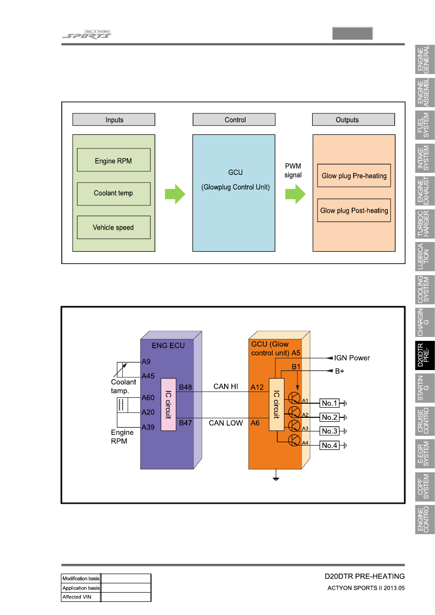
1) Input/Output Diagram of Glow Plug Control Unit
2) System Diagram

10-6
3) Circuit Diagram

10-7
1413-00
4) Operation
Glow plug is installed in the cylinder head. It enhances the cold starting performance and reduces the
exhaust gas during cold starting.
ECU receives the data (engine rpm, coolant temperature, vehicle speed) through CAN lines. Based on
the data, GCU controls the pre-glow, cranking and post-glow. It also checks the glow plugs, and sends
the result to ECU.
(1) Temperature/Current Properties of GCU
GCU increases the temperature of glow plug very rapidly (approx. 2 seconds up to 100
FETs (similar to transistor) for each cylinder are integrated in GCU. During the pre-glow
period, battery voltage is supplied to the glow plugs directly to heat them rapidly.
After getting the desired temperature by pre-glowing, the temperature is controlled by duty
ratio.
Step 1:
Step 2 & 3:
Step 4:
This shows the supplying voltage and time by GCU in each step. The step 4 is the period to keep the
temperature.
-
Step 1: I1
Step 2: I2
Step 3: I3
Step 4: I4
10-8
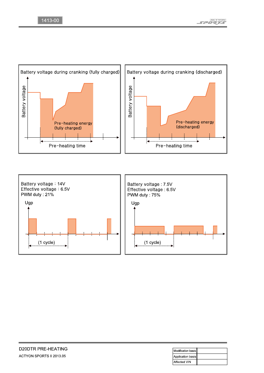
(2) Pre-heating time control based on battery voltage
GCU monitors the battery voltage. If it is low, GCU extends the pre-heating time.
GCU monitors the energy to glow plugs (the amount of pre-heating energy is always same).
-
-
GCU monitors the battery voltage. If it is low, GCU extends the pre-heating time to get enough
energy.
-
GCU monitors the battery voltage. If it is low, GCU increases PWM duty..
-
Нет комментариевНе стесняйтесь поделиться с нами вашим ценным мнением.
Текст