Isuzu D-Max / Isuzu Rodeo (TFR/TFS). Manual — part 785
6A–20
ENGINE MECHANICAL (6VD1 3.2L)
Common Chamber
Removal
1. Disconnect battery ground cable.
2. Remove air cleaner duct assembly.
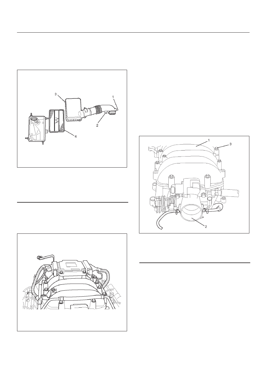
060RW079
Legend
(1) Positive Crankcase Ventilation Hose Connector
(2) Intake Air Temperature Sensor
(3) Air Cleaner Duct Assembly
(4) Air Cleaner Element
3. Remove the ECM.
D
Disconnect the two connectors from the ECM.
D
Remove fixing bolts on the common chamber.
D
Remove fixing bolts for ground cable.
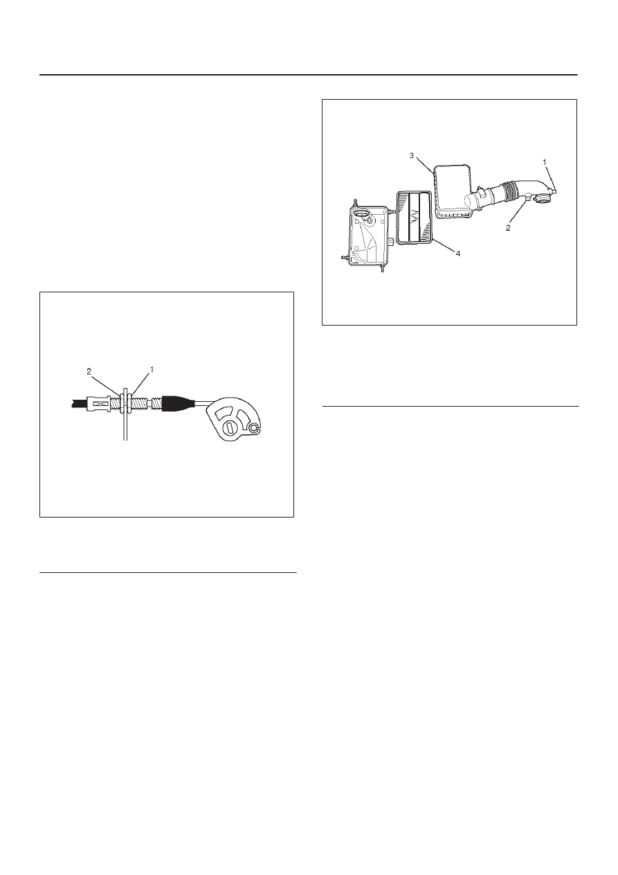
060RW025
4. Disconnect accelerator pedal cable from throttle body
and cable bracket.
5. Disconnect vacuum booster hose from common
chamber.
6. Disconnect connector from manifold absolute
pressure sensor, idle air control valve, throttle
position sensor, solenoid valve, electric vacuum
sensing valve.
7. Disconnect vacuum hose on canister VSV and
positive crankcase ventilation hose, fuel rail
assembly with pressure control valve bracket.
8. Remove ventilation hose from throttle valve and
intake duct and remove water hose.
9. Remove the four throttle body fixing bolts.
10. Remove exhaust gas recirculation valve assembly
fixing bolt and nut on common chamber.
11. Remove two bolts from common chamber rear side
for remove fuel hose bracket.
12. Remove common chamber four bolts and four nuts
then remove the common chamber.
025RW001
Legend
(1) Common Chamber
(2) Throttle Valve Assembly
(3) Bolt
Installation
1. Install common chamber and tighten bolts and nuts to
the specified torque.
Torque :
Bolt : 25 N·m (2.6 kg·m/18 lb ft)
Nut : 25 N·m (2.6 kg·m/18 lb ft)
2. Install fuel hose bracket and tighten bolts to specified
torque.
Torque : 10 N·m (1.0 kg·m/89 lb in)
3. Install throttle body and tighten bolts to the specified
torque.
Torque : 25 N·m (2.6 kg·m/18 lb ft)
4. Install ventilating hose to throttle valve and intake
duct.
6A–21
ENGINE MECHANICAL (6VD1 3.2L)
5. Connect vacuum hoses on canister VSV and positive
crankcase ventilation hose. Tighten bolts for fuel rail
assembly with pressure control valve bracket.
Torque : 25 N·m (2.5 kg·m/18 lb ft)
6. Connect each connector without fail.
7. Connect vacuum booster hose.
8. Install the ECM.
D
Tighten the four bolts.
Torque : 10 N·m (1.0 kg·m/7 lb ft)
D
Connect the two connectors.
D
Tighten the two ground cable bolts.
9. Connect accelerator pedal cable.
Don’t need accelerator pedal cable adjustment.
D
Tighten nut and lock nut.
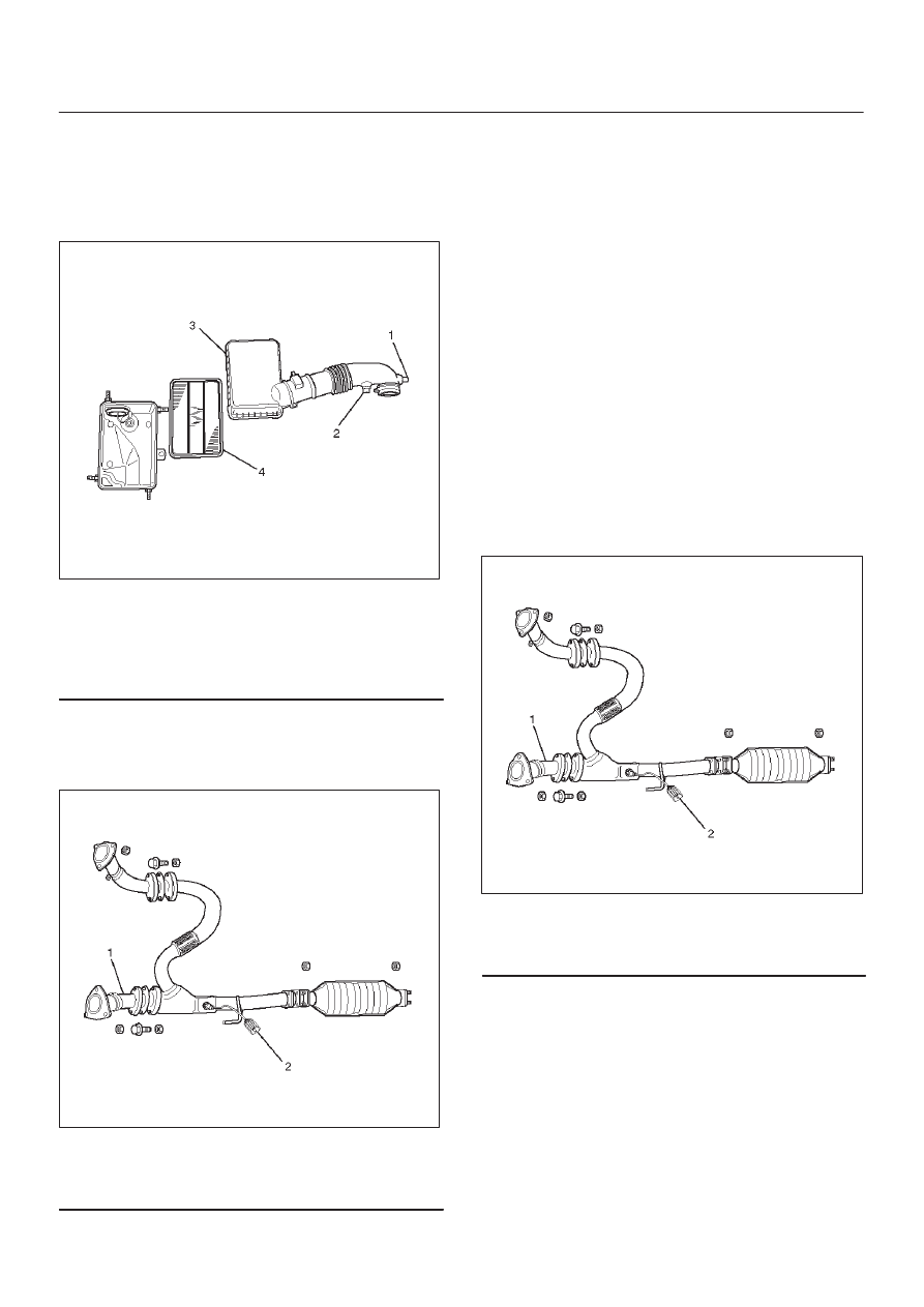
060RW093
Legend
(1) Lock Nut
(2) Nut
10. Install air cleaner duct assembly.
060RW079
Legend
(1) Positive Crankcase Ventilation Hose Connector
(2) Intake Air Temperature Sensor
(3) Air Cleaner Duct Assembly
(4) Air Cleaner Element.
6A–22
ENGINE MECHANICAL (6VD1 3.2L)
Exhaust Manifold LH
Removal
1. Disconnect battery ground cable.
2. Remove air cleaner duct assembly.
060RW079
Legend
(1) Positive Crankcase Ventilation Hose Connector
(2) Intake Air Temperature Sensor
(3) Air Cleaner Duct Assembly
(4) Air Cleaner Element
3. Disconnect O
2
sensor connector.
4. Remove exhaust front pipe three stud nuts from
exhaust side and two nuts from rear end of exhaust
front pipe.
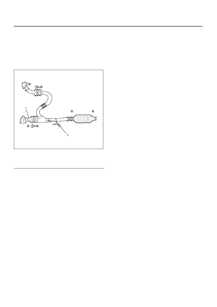
060RW101
Legend
(1) Exhaust Front Pipe LH
(2) O
2
Sensor
5. Remove heat protector two fixing bolts then the heat
protector.
6. Remove a bolt on engine LH side for air conditioner
(A/C) compressor bracket and loosen two bolts for
A/C compressor then move A/C compressor to front
side.
7. Remove exhaust manifold eight fixing nuts and
remove exhaust manifold from the engine.
Installation
1. Install exhaust manifold and tighten exhaust manifold
fixing nuts to the specified torque with new nuts.
Torque: 57 N·m (5.8 kg·m/42 lb ft)
2. Install heat protector.
3. Install exhaust front pipe and tighten three stud nuts
and two nuts to the specified torque.
Torque :
Stud nuts: 67 N·m (6.8 kg·m/49 lb ft)
Nuts: 43 N·m (4.4 kg·m/32 lb ft)
060RW101
Legend
(1) O
2
Sensor
(2) Exhaust Front Pipe LH
4. Set A/C compressor to normal position and tighten
two bolts and a bolt to the specified torque.
Torque : 40 N·m (4.1 kg·m/30 lb ft)
5. Reconnect O
2
sensor connector.
6. Install air cleaner duct assembly.
6A–23
ENGINE MECHANICAL (6VD1 3.2L)
Exhaust Manifold RH
Removal
1. Disconnect battery ground cable.
2. Remove torsion bar. Refer to removal procedure in
Front Suspension section.
3. Remove exhaust front pipe three stud nuts and two
nuts then disconnect exhaust front pipe.
060RW101
Legend
(1) Exhaust Front Pipe RH
(2) O
2
Sensor
4. Remove heat protector two fixing bolts then the heat
protector.
5. Remove exhaust manifold eight fixing nuts then the
exhaust manifold.
Installation
1. Install exhaust manifold and tighten bolts to the
specified torque.
Torque : 57 N·m (5.8 kg·m/42 lb ft)
2. Install heat protector
3. Install exhaust front pipe and tighten three stud nuts
and two nuts to the specified torque.
Torque:
Stud nuts: 67 N·m (6.8 kg·m/49 lb ft)
Nuts: 43 N·m (4.4 kg·m/32 lb ft)
4. Install the torsion bar and readjust the vehicle height.
Refer to installation and vehicle height adjustment
procedure for front suspension.
Нет комментариевНе стесняйтесь поделиться с нами вашим ценным мнением.
Текст