Isuzu D-Max / Isuzu Rodeo (TFR/TFS). Manual — part 41

4JA1-TC/4JH1-TC ENGINE DRIVEABILITY AND EMISSIONS
6E–159
Condition for setting the DTC and action taken when the DTC sets
Circuit Description
The CKP sensor is located on top of the flywheel
housing of the flywheel and fixed with a bolt. The CKP
sensor is of the magnet coil type. The inductive pickup
sensors four gaps in the flywheel exciter ring and is
used to determine the engine speed and engine
cylinder top dead center.
If the CKP sensor harness or sensor malfunction is
detected during engine run, DTC P0335 (Symptom
Code B) is stored.
If the CKP sensor harness or sensor malfunction is
detected during engine cranking, DTC P0335
(Symptom Code D) is stored.
If the CKP sensor signal frequency is excessively high
or engine over-running, DTC P0335 (Symptom Code E)
is stored.
Diagnostic Aids
An intermittent may be caused by the following:
• Poor connections.
• Misrouted harness.
• Rubbed through wire insulation.
• Broken wire inside the insulation.
Check for the following conditions:
• Poor connection at ECM-Inspect harness connectors
for backed out terminals, improper mating, broken
locks, improperly formed or damaged terminals, and
poor terminal to wire connection.
• Damaged harness-Inspect the wiring harness for
damage. If the harness appears to be OK, observe
the “Engine Speed” display on the Tech2 while
moving connectors and wiring harness related to the
sensor.
Diagnostic Trouble Code (DTC) P0335 (Symptom Code B) (Flash Code 43)
Crankshaft Position Sensor Circuit Malfunction
Diagnostic Trouble Code (DTC) P0335 (Symptom Code D) (Flash Code 43)
Crankshaft Position Sensor Malfunction
Flash
Code
Code
Symptom
Code
MIL
DTC Name
DTC Setting Condition
Fail-Safe (Back Up)
43
P0335
B
ON
Crankshaft Position Sensor
Circuit Malfunction
1. Engine speed is more than
665rpm.
2. CKP sensor pulse width
error.
When pump camshaft speed
sensor is OK:
ECM uses doubled pump cam-
shaft speed as substitute
engine speed.
When pump camshaft speed
sensor is not OK:
1. MAB (fuel cutoff solenoid
valve) is operated.
2. Desired injection quantity
becomes 0mg/strk.
D
ON
Crankshaft Position Sensor
Circuit Malfunction
1. No pump camshaft speed
sensor error.
2. “Crankshaft Position Sen-
sor Circuit Malfunction
(Symptom Code B)” is not
stored.
3. Engine speed is 0rpm.
4. Doubled pump camshaft
speed is more than 50rpm.
When pump camshaft speed
sensor is OK:
ECM uses doubled pump cam-
shaft speed as substitute
engine speed.
Other than pump camshaft
speed sensor is OK:
Fuel injection quantity is
reduced.
E
ON
Engine Speed Input Circuit
Range/Performance
Engine speed is more than
5700rpm.
When intermittent malfunction:
1. MAB (fuel cutoff solenoid
valve) is operated.
2. Desired injection quantity
becomes 0mg/strk.
When preliminary malfunction:
ECM uses doubled pump cam-
shaft speed as substitute
engine speed.
Step
Action
Value(s)
Yes
No
1
Was the “On-Board Diagnostic (OBD) System Check”
performed?
—
Go to Step 2
Go to On Board
Diagnostic
(OBD) System
Check
6E–160
4JA1-TC/4JH1-TC ENGINE DRIVEABILITY AND EMISSIONS
2
1. Connect the Tech 2.
2. Review and record the failure information.
3. Select “F0: Read DTC Infor As Stored By ECU” in
“F0: Diagnostic Trouble Codes”.
Is the DTC P0335 (Symptom Code B) or P0335
(Symptom Code D) stored as “Present Failure”?
—
Go to Step 3
Refer to
Diagnostic Aids
and Go to Step
3
3
1. Using the Tech 2, ignition “On” and engine “Off”.
2. Select “F1: Clear DTC Information” in “F0:
Diagnostic Trouble Codes” with the Tech 2 and
clear the DTC information.
3. Operate the vehicle and monitor the “F0: Read
DTC Infor As Stored By ECU” in the “F0:
Diagnostic Trouble Codes”.
Was the DTC P0335 (Symptom Code B) or P0335
(Symptom Code D) stored in this ignition cycle?
—
Go to Step 4
Refer to
Diagnostic Aids
and Go to Step
4
4
Check for poor/faulty connection at the CKP sensor or
ECM connector. If a poor/faulty connection is found,
repair the faulty terminal.
Was the problem found?
—
Verify repair
Go to Step 5
5
Visually check the CKP sensor. If a faulty installation is
found, repair as necessary.
Was the problem found?
—
Verify repair
Go to Step 6
6
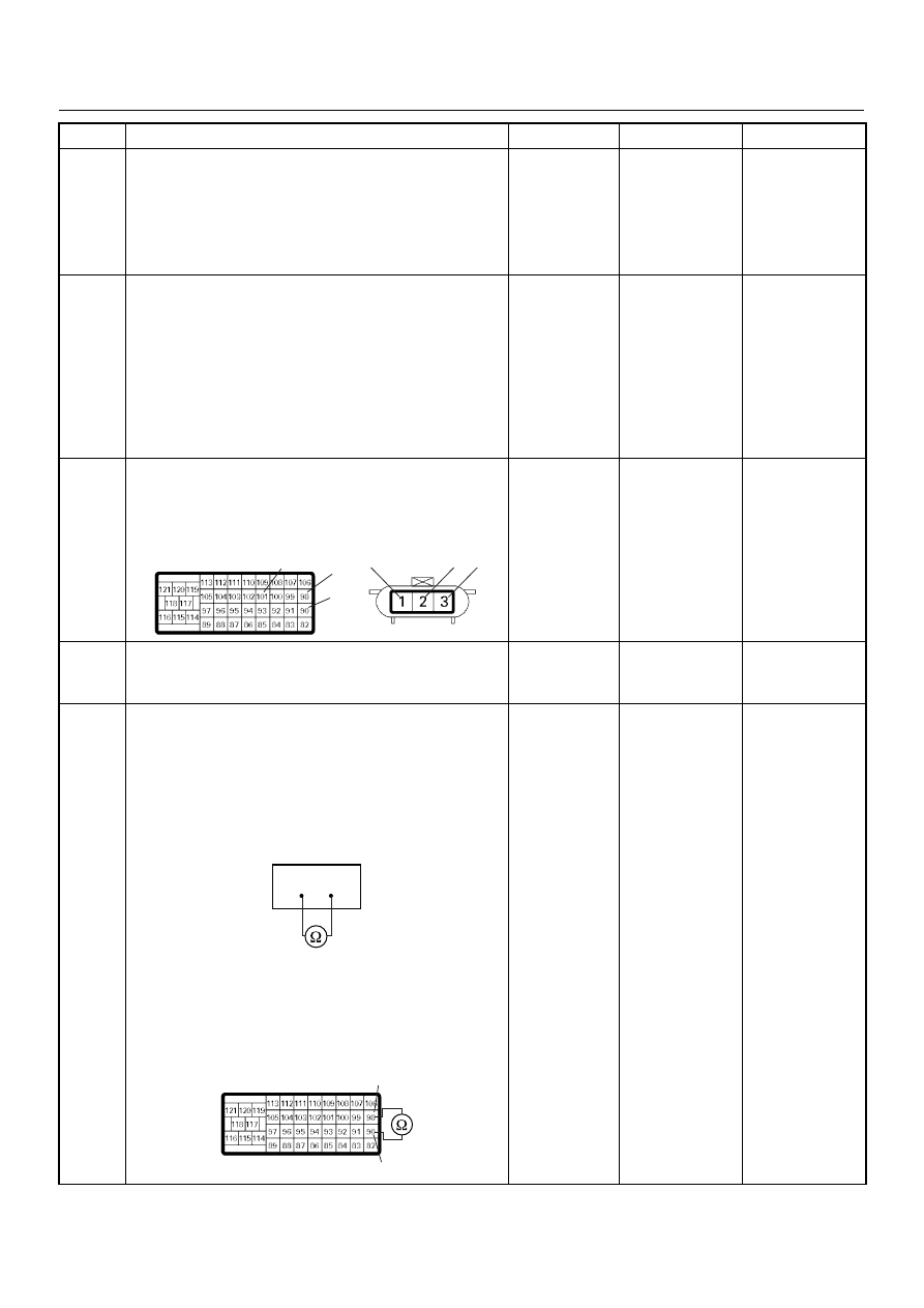
Using the DVM and check the CKP sensor circuit.
Breaker box is available:
1. Ignition “Off”, engine “Off”.
2. Install the breaker box as type A. (ECM
disconnected) Ref. Page 6E-81
3. Check the resistance of the CKP sensor.
Was the DVM indicated specified value?
Breaker box is not available:
1. Ignition “Off”, engine “Off”.
2. Disconnect the ECM connector.
3. Check the resistance of the CKP sensor.
Was the DVM indicated specified value?
Approximately
0.9k
Ω at 20°C
Go to Step 10
Go to Step 7
Step
Action
Value(s)
Yes
No
101
90
98
2
3
1
E-9
C-57(B)
90
98
90
98
C-57(B)
4JA1-TC/4JH1-TC ENGINE DRIVEABILITY AND EMISSIONS
6E–161
7
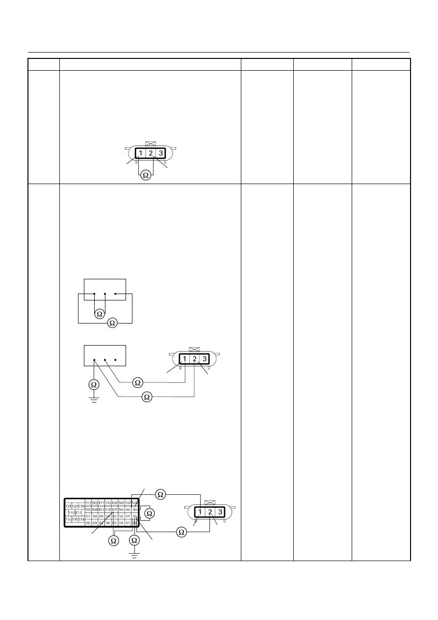
Using the DVM and check the CKP sensor circuit.
1. Ignition “Off”, engine “Off”.
2. Disconnect the CKP sensor connector.
3. Check the resistance of the CKP sensor.
Was the DVM indicated specified value?
Approximately
0.9k
Ω at 20°C
Go to Step 8
Go to Step 14
8
Using the DVM and check the CKP sensor circuit.
Breaker box is available:
1. Ignition “Off”, engine “Off”.
2. Install the breaker box as type A. (ECM
disconnected) Ref. Page 6E-81
3. Disconnect the CKP sensor connector.
4. Check the circuit for open, short to sensor wire or
short to ground circuit.
Was the problem found?
Breaker box is not available:
1. Ignition “Off”, engine “Off”.
2. Disconnect the ECM connector.
3. Disconnect the CKP sensor connector.
4. Check the circuit for open, short to sensor wire or
short to ground circuit.
Was the problem found?
—
Repair faulty
harness and
verify repair
Go to Step 9
Step
Action
Value(s)
Yes
No
1
2
E-9
90 98 101
90 98 101
1
2
E-9
101
98
90
2
1
E-9
C-57(B)
6E–162
4JA1-TC/4JH1-TC ENGINE DRIVEABILITY AND EMISSIONS
9
Using the DVM and check the CKP sensor circuit.
1. Ignition “On”, engine “Off”.
2. Disconnect the CKP sensor connector.
3. Check the circuit for short to power supply circuit.
If the DVM indicated out of specified value, repair
faulty harness and verify repair.
Is the action complete?
Less than 1V
Verify repair
—
10
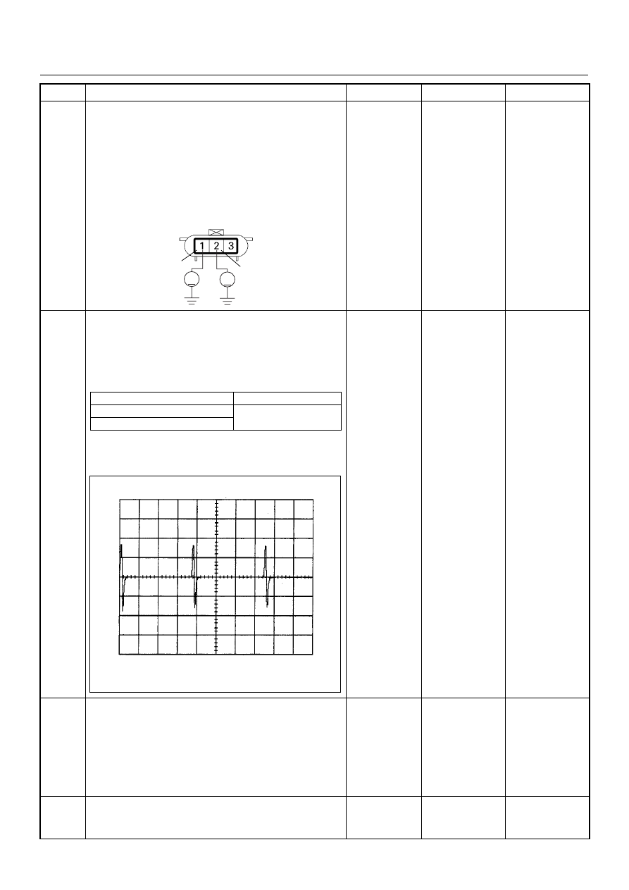
Using the DVM and check the CKP sensor signal.
1. Ignition “On”, engine “On”.
2. Measure the CKP output voltage at the sensor
and ECM.
Does the tester indicate standard voltage?
If a oscilloscope is available, monitor the CKP sensor
signal. Does the oscilloscope indicate correct wave
form?
Go to Step 13
Go to Step 11
11
Remove the CKP sensor from the flywheel housing
and visually check.
Check for the following conditions.
• Objects sticking the CKP sensor.
• Objects sticking the CKP sensor pulser.
If a problem is found, repair as necessary.
Was the problem found?
—
Verify repair
Go to Step 12
12
Check the CKP sensor shield wire for open or short
circuit.
Was the problem found?
—
Repair faulty
harness and
verify repair
Go to Step 13
Step
Action
Value(s)
Yes
No
1
2
V
V
E-9
Measurement Point
Voltage (V) (AC Range)
At CKP sensor terminal 2 & 1
Approximately 1.0 V at
2000rpm
At ECM C57 connector 90 & 98
CKP Sensor Reference Wave Form
0V
→
Measurement Terminal: 90 (+) 98(-)
Measurement Scale: 20V/div
2.0ms/div
Measurement Condition: Engine speed at 2000rpm
Нет комментариевНе стесняйтесь поделиться с нами вашим ценным мнением.
Текст