Isuzu D-Max / Isuzu Rodeo (TFR/TFS). Manual — part 1226

8-244 ELECTRICAL-BODY AND CHASSIS
Installation
Rubber Seal
Be absolutely sure that the fuel tank unit rubber seal is
correctly seated.
Connector
Be absolutely sure that the fuel tank unit connector is securely
connected.
This will prevent a poor contact and an open circuit.
VEHICLE SPEED SENSOR (INSTALLED
ON THE TRANSMISSION)
Removal
1. Disconnect the connector.
2. Remove the vehicle speed sensor body by rotating it.
Installation
To Install, follow the removal steps in the reverse order, noting
the following point.
Tighten the vehicle speed sensor to the specified torque.
Vehicle Speed Sensor Tightening Torque
N
×m (kgf×m/lb.ft)
25
± 4.9 (2.5 ± 0.5/18 ± 3.6)
ELECTRICAL-BODY AND CHASSIS 8-245
INSPECTION AND REPAIR
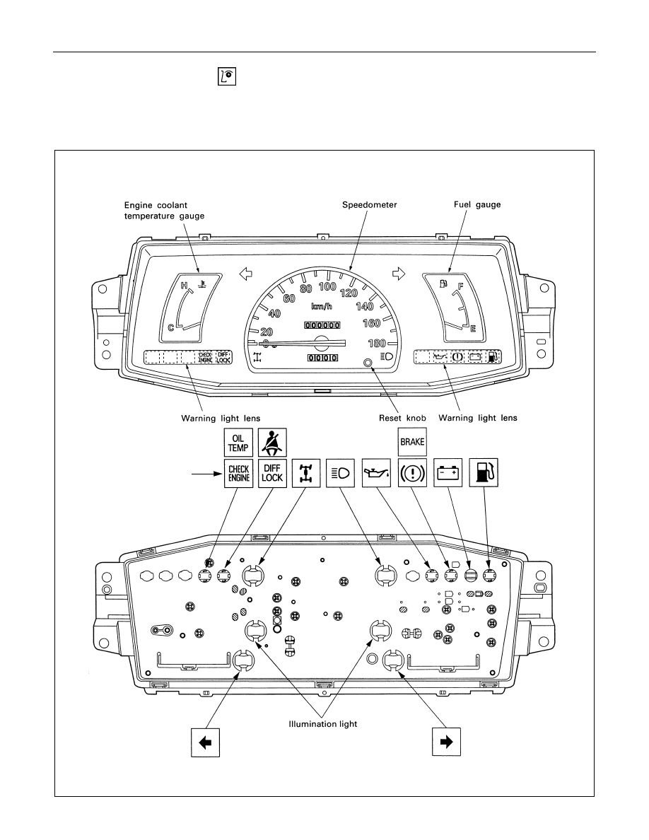
Warning, indicator and illumination light position
W/O tachometer
(This illustration is based on the Km/h meter)
(For South Africa only)
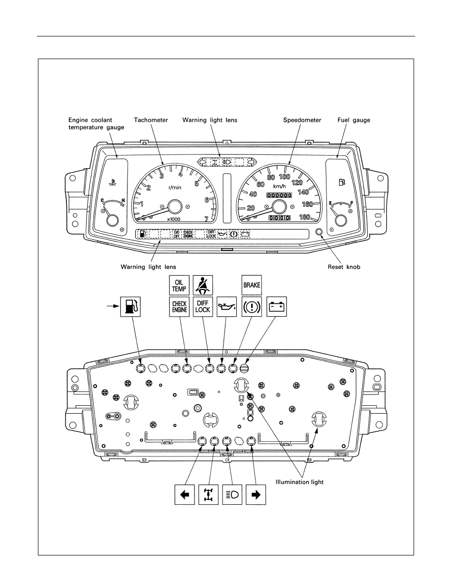
8-246 ELECTRICAL-BODY AND CHASSIS
W/ Tachometer
(This illustration is based on the Km/h meter)
(For South Africa
only)

ELECTRICAL-BODY AND CHASSIS 8-247
Meter connector pin arrangement
W/O Tachometer-1
Connector
Ter-
No.
minal No.
B-24
1
Ground
2
Ignition
3
-
4
-
5
-
6
Engine coolant temperature gauge
7
-
8
-
9
Check engine warning light
10
Diff. lock indicator light (South Africa only)
11
High-beam indicator light (+)
12
High-beam indicator light (-)
13
Illumination light (+)
14
Illumination light (-)
15
4WD indicator light
16
Turn signal indicator light (left)
Connector
Ter-
No.
minal No.
B-23
1
Turn signal indicator light (right)
2
-
3
-
4
-
5
Ground
6
-
7
Ignition
8
Speedometer
9
Speedometer
10
Oil pressure warning light
11
Fuel gauge
12
Brake warning light
13
Charge warning light
14
-
15
-
16
Fuel warning light (Except Chile)
Нет комментариевНе стесняйтесь поделиться с нами вашим ценным мнением.
Текст