Isuzu D-Max / Isuzu Rodeo (TFR/TFS). Manual — part 1898

7A4-24 UNIT REPAIR (JR405E)
Disassembly steps
•
Remove the oil filter from the control valve lower body.
244L300009
Legend
1. Oil filter
2. Separation plate
•
Remove the control valve from the control valve lower
body.
NOTE:
Place the control valve where it will not get mixed up with
the other parts.
Inspection
Valve
Inspect each of the valves for denting and other damage.
Spring
Inspect each of the springs for wear and fatigue.
UNIT REPAIR (JR405E) 7A4-25
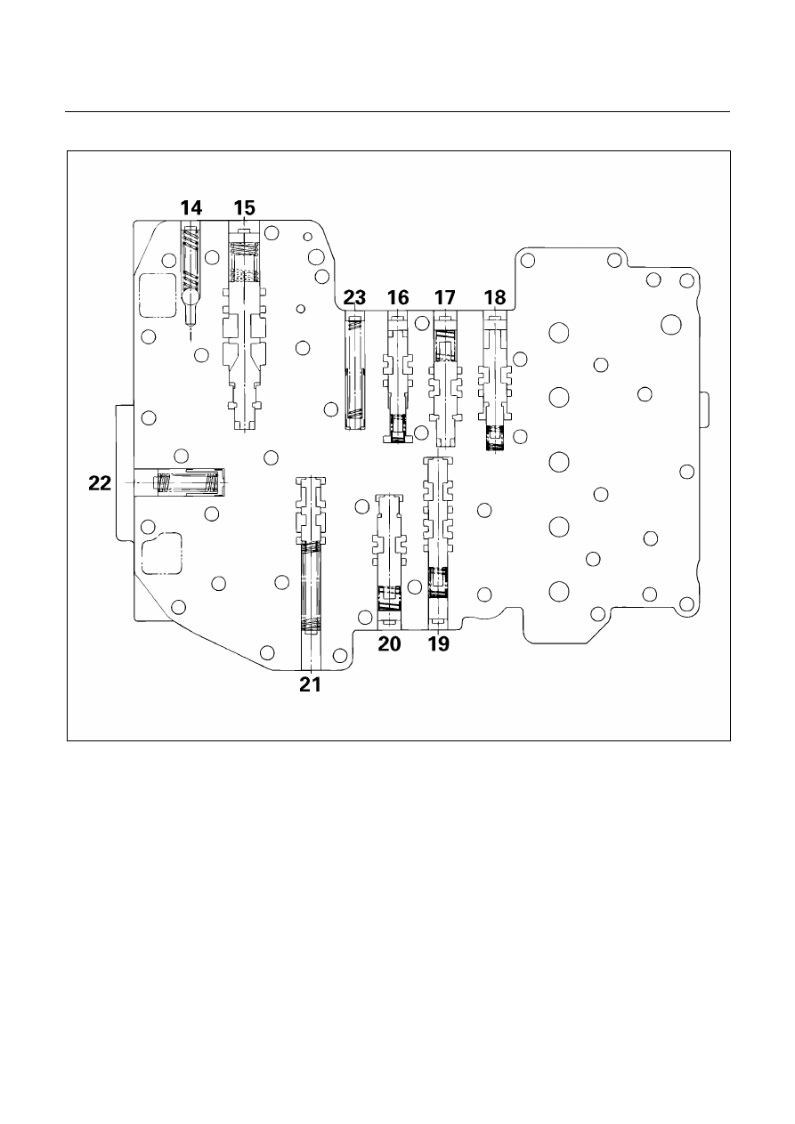
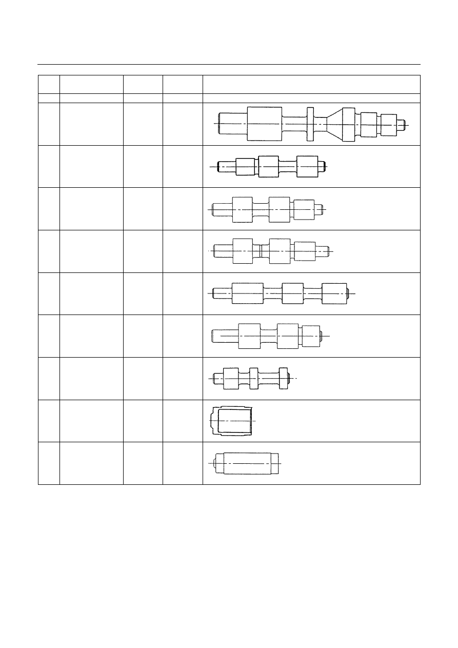
Valve specifications
244L300008
7A4-26 UNIT REPAIR (JR405E)
No.
Valve
nomenclature
Diameter
(mm / in)
Length
(mm / in)
Configuration
14 Pressure
relief
----
----
15
Pressure
regulator
16.0 /
0.630
89.5 /
3.524
16
Low and reverse
brake fail (A)
10.0 /
0.394
52.0 /
2.047
17 Fail
12.0 /
0.472
53.5 /
2.106
18
Low and reverse
brake amp
12.0 /
0.472
55.5 /
2.185
19
2 – 4 brake fail
(A)
10.0 /
0.394
65.5 /
2.579
20
Low clutch amp
(B)
12.0 /
0.472
53.0 /
2.087
21
Torque
converter relief
10.0 /
0.394
37.4 /
1.472
22
2 – 4 brake
solenoid
accumulator
14.0 /
0.551
19.5 /
0.768
23
High clutch
accumulator
10.0 /
0.394
31.0 /
1.220

UNIT REPAIR (JR405E) 7A4-27
Spring specifications
No. Valve
nomenclature
Free length
(mm / in)
Outside
diameter (mm
/ in)
Linear
diameter (mm
/ in)
Number of
coils
14
Pressure relief
49.0 / 1.929
7.6 / 0.299
1.1 / 0.043
17.3
15
Pressure regulator
30.5 / 1.201
14.0 / 0.551
1.4 / 0.055
5.7
16
Low and reverse brake fail (A)
22.0 / 0.866
7.0 / 0.276
0.6 / 0.024
10.0
17
Fail
23.0 / 0.906
11.0 / 0.433
0.5 / 0.020
13.2
18
Low and reverse brake amp
19.5 / 0.768
7.9 / 0.311
0.5 / 0.020
6.9
19 2
– 4 brake fail (A)
24.8 / 0.976
8.5 / 0.335
0.9 / 0.035
7.8
20
Low clutch amp (B)
26.0 / 1.024
11.0 / 0.433
0.5 / 0.020
6.9
21
Torque converter relief
More than 47.2
/ 1.858
9.2 / 0.362
1.6 / 0.063
20.2
22 2
– 4 brake solenoid accumulator
31.4 / 1.236
9.8 / 0.386
1.3 / 0.051
9.3
23
High clutch accumulator
51.0 / 2.008
6.5 / 0.256
0.8 / 0.031
23.5
Oil pressure switch
Apply compressed air (392 kPa/4.0 kg/cm
2
) to the oil pressure
switch to check the oil pressure switch continuity between the
connector and screw.
244L300011
Oil temperature sensor (harness assembly)
Check the oil temperature sensor resistance between harness
terminals 7 and 6 (ground).
Oil temperature sensor resistance: 2,400
∼
∼
∼
∼2,600 ohms
(20
℃
℃
℃
℃)
Solenoid
Measure the resistance of each solenoid.
Resistance:
Brown connector – 3.0
∼∼∼∼
3.4 ohms (20
°°°°
C)
Gray connector – 12.0
∼∼∼∼
13.2 ohms (20
°°°°
C)
White connector – 12.2
∼∼∼∼
13.4 ohms (20
°°°°
C)
Reassembly steps
•
Coat the parts with ATF before installing them.
•
Install the control valve to the control valve lower body.
•
Install the oil filter to the control valve lower body.
Нет комментариевНе стесняйтесь поделиться с нами вашим ценным мнением.
Текст