Isuzu D-Max / Isuzu Rodeo (TFR/TFS). Manual — part 210
ENGINE DRIVEABILITY AND EMISSIONS
6E–81
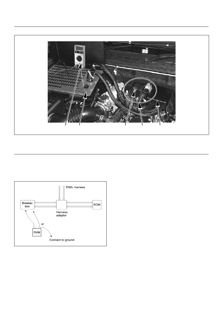
Breaker Box Connection Type B
Breaker box connection type B, check for “short to
power supply circuit” and “power, signal voltage check”
between the engine control module (ECM) and
electrical components.
4
3
1
5
2
(1) Engine Control Module (ECM)
(2) Harness Adapter
(3) Breaker Box
(4) Digital Voltage Meter
(5) ECM - Harness Adapter Connection
6E–82
ENGINE DRIVEABILITY AND EMISSIONS
ON-BOARD DIAGNOSTIC (OBD) SYSTEM CHECK
Circuit Description
The on-board diagnostic system check is the starting
point for any driveability complaint diagnosis. Before
using this procedure, perform a careful visual/physical
check of the ECM and engine grounds for cleanliness
and tightness.
The on-board diagnostic system check is an organized
approach to identifying a problem created by an
electronic engine control system malfunction.
Diagnostic Aids
An intermittent may be caused by a poor connection,
rubbed-through wire insulation or a wire broken inside
the insulation. Check for poor connections or a
damaged harness. Inspect the ECM harness and
connector for improper mating, broken locks, improperly
formed or damaged terminals, poor terminal-to-wire
connection, and damaged harness.
Test Description
Number(s) below refer the step number(s) on the
Diagnostic Chart:
1. The Check Engine Lamp (MIL) should be ON steady
with the ignition “On”, engine “Off”. If not, “No Check
Engine Lamp (MIL)” chart should be used to isolate the
malfunction.
2. Checks the Class 2 data circuit and ensures that the
ECM is able to transmit serial data.
3. This test ensures that the ECM is capable of
controlling the Check Engine Lamp (MIL) and the Check
Engine Lamp (MIL) driver circuit is not shorted to
ground circuit.
4. If the engine will not start, “Engine Cranks But Will
Not Run” chart should be used to diagnose the fault.
6. The Tech2 parameters which is not within the typical
range may help to isolate the area which is causing the
problem.
12. This vehicle is equipped with ECM which utilizes an
electrically erasable programmable read only memory
(EEPROM).
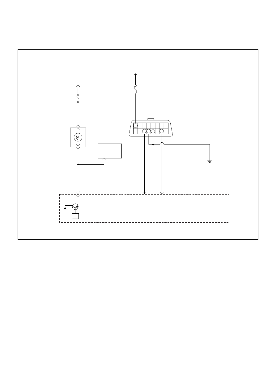
Buttery
Voltage
0.5
RED/
YEL
Engine
Room-RH
µP
J2-32
7
0.5
BRN/
YEL
Engine
Control
Module
(ECM)
Check
Engine
Lamp
Imnobiliser
Control
Unit
METER
15A
Ignition
SW
0.5
BLU
J2-4
0.5
GRN
J2-30
Diag
SW
Class 2
Serial
Data
0.85 BLK
Diagnostic
Comectar
16 15 14 13 12 11 10 9
8 7 6 5 4 3 2 1
METER
10A
ENGINE DRIVEABILITY AND EMISSIONS
6E–83
ON-BOARD DIAGNOSTIC (OBD) SYSTEM CHECK
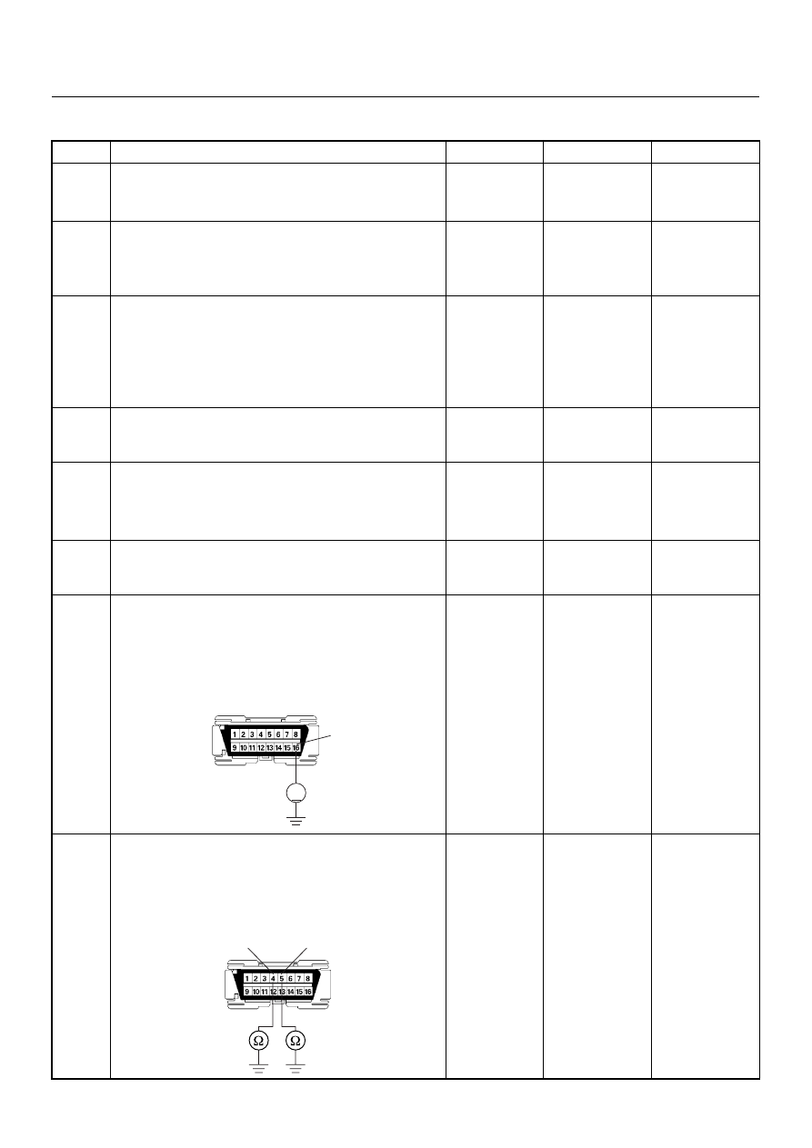
Step
Action
Value(s)
Yes
No
1
1. Ignition “On”, engine “Off”.
2. Check the “CHECK ENGINE” lamp (MIL).
Does the “CHECK ENGINE” lamp turn “On”?
—
Go to Step 2
Go to No
CHECK
ENGINE Lamp
2
1. Using the Tech 2, ignition “On” and engine “Off”.
2. Attempt to display “Engine Data” with the Tech 2.
Does the Tech 2 display “Engine Data” and “O
2
Sensor Data”?
—
Go to Step 3
Go to Step 7
3
1. Using the Tech 2, ignition “On” and engine “Off”.
2. Select the “Miscellaneous Test” and perform the
“Malfunction Indicator Lamp” in “Lamps”.
3. Operate the Tech 2 in accordance with the Tech 2
instructions.
Does the “CHECK ENGINE” lamp turn “Off”?
—
Go to Step 4
Go to CHECK
ENGINE LAMP
On Steady
4
Attempt to start the engine.
Does the engine start and continue to “Run”?
—
Go to Step 5
Go to Engine
Cranks But Will
Not Run
5
1. Using the Tech 2, ignition “On” and engine “Off”.
2. Select the “Read DTC Infor By Priority” in
“Diagnostic Trouble Code”.
3. Are any DTCs stored?
—
Go to DTC
Chart
Go to Step 6
6
Compare typical scan data values displayed on the
Tech 2 “Engine Data” and “O
2
Sensor Data”.
Are the displayed values within the range?
—
Refer to
SYMPTOM
DIAGNOSIS
Refer to
TYPICAL
SCAN DATA
7
Using the DVM and check the data link connector
power supply circuit.
1. Ignition “Off”, engine “Off”.
2. Check the circuit for open circuit.
Was the problem found?
—
Repair faulty
harness and
verify repair
Go to Step 8
8
Using the DVM and check the data link connector
ground circuit.
1. Ignition “Off”, engine “Off”.
2. Check the circuit for open circuit.
Was the problem found?
—
Repair faulty
harness and
verify repair
Go to Step 9
V
16
B58
5
4
B58
6E–84
ENGINE DRIVEABILITY AND EMISSIONS
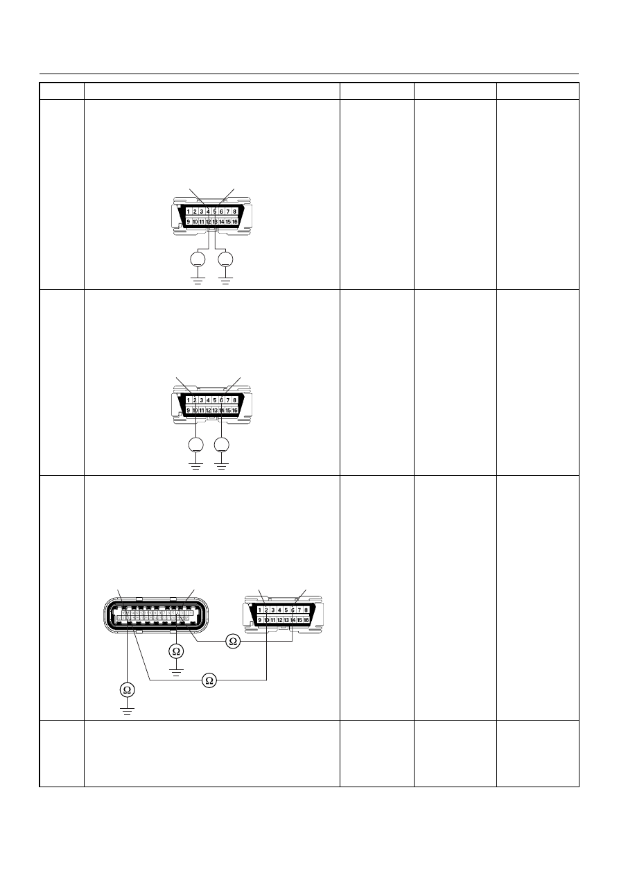
9
Using the DVM and check the data link connector
ground circuit.
1. Ignition “On”, engine “Off”.
2. Check the circuit for short to power supply circuit.
Was the DVM indicated specified value?
Less than 1V
Go to Step 10
Repair faulty
harness and
verify repair
10
Using the DVM and check the data link connector
communication circuit.
1. Ignition “On”, engine “Off”.
2. Check the circuit for short to power supply circuit.
Was the DVM indicated battery voltage?
—
Repair faulty
harness and
verify repair
Go to Step 11
11
Using the DVM and check the data link connector
communication circuit.
1. Ignition “Off”, engine “Off”.
2. Disconnect the ECM connector.
3. Check the circuit for open or short to ground
circuit.
Was the problem found?
—
Repair faulty
harness and
verify repair
Go to Step 12
12
Is the ECM programmed with the latest software
release?
If not, download the latest software to the ECM using
the “SPS (Service Programming System)”.
Was the problem solved?
—
Verify repair
Go to Step 13
Step
Action
Value(s)
Yes
No
V
V
5
4
B58
V
V
B58
6
2
B58
C56(J2)
4
30
6
2
Нет комментариевНе стесняйтесь поделиться с нами вашим ценным мнением.
Текст