Isuzu D-Max / Isuzu Rodeo (TFR/TFS). Manual — part 1131
ELECTRICAL-BODY AND CHASSIS 8-281
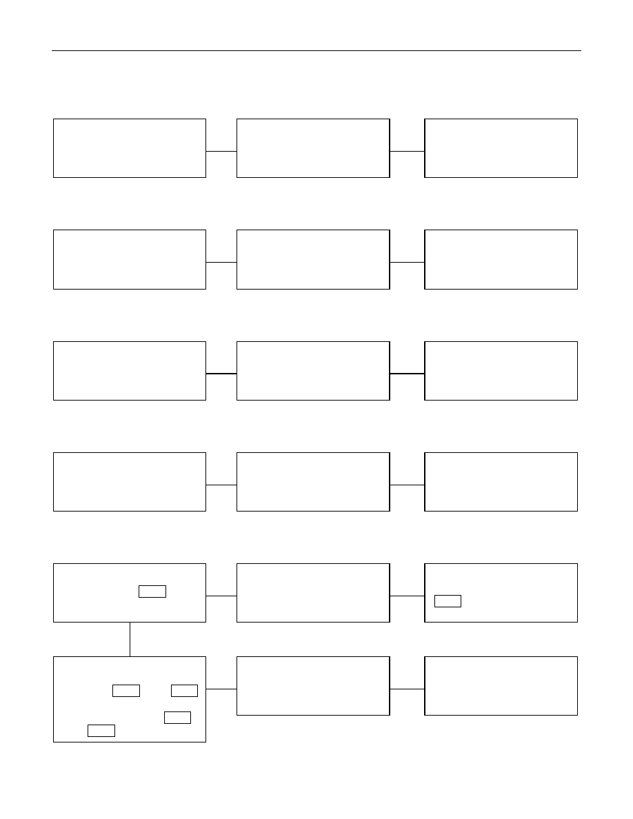
3. Driver’s side door does not get locked (or unlocked)
CheckpointTrouble Cause
Count
ermeasure
Replace the door lock SW.
Door lock SW. function
SW. malfunction
NG
4. FRT passenger’s side door does not get locked (or unlocked)
Replace the FRT passenger’s
side door lock actuator
FRT passenger’s side door
lock actuator function
Actuator malfunction
NG
5. RR door-RH does not get locked (or unlocked)
Replace the RR door lock
actuator-RH
RR door lock actuator-RH
function
Actuator malfunction
NG
6. RR door-LH does not get locked (or unlocked)
Replace the RR door lock
actuator-LH
RR door lock actuator-LH
function
Actuator malfunction
NG
7. Door lock does not operate when operated from the driver’s seat side
Repair grounding point
(
B-28
) contact
Poor grounding point contact
NG
Replace the door lock SW.
Continuity between the door
lock SW. side connector
terminals 1
D-4
and 2
D-4
when the SW is locked and
between is unlocked 3
D-4
and 2
D-4
when the SW.
SW. malfunction
NG
OK
Grounding point (
B-28
)
8-282 ELECTRICAL-BODY AND CHASSIS
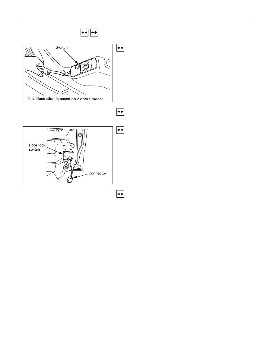
REMOVAL AND INSTALLATION
DRIVER SEAT SIDE POWER WINDOW &
DOOR LOCK SWITCH
Removal
1. Remove the switch by pushing the spring with the tip of a
screwdriver.
2. Disconnect the connector.
Installation
To install, follow the removal steps in the reverse order.
DRIVER’S SIDE DOOR LOCK SWITCH
Removal
1. Door Lock ASM
• Refer to the removal steps of the DOORS in section 10
“BODY”.
2. Door Lock Switch
Installation
To install, follow the removal steps in the reverse order.
ELECTRICAL-BODY AND CHASSIS 8-283
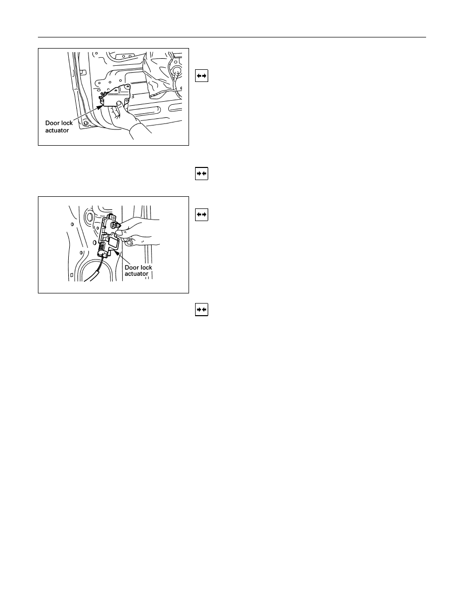
FRT PASSENGER’S SIDE DOOR LOCK
ACTUATOR
Removal
1. Door Lock ASM
• Refer to the removal steps of the DOORS in Section 10
“BODY”.
2. Door Lock Actuator
• Remover the actuator fixing bolts.
• Disconnect the door lock link rod.
• Disconnect the actuator connector.
Installation
To install, follow the removal steps in the reverse order.
RR DOOR LOCK ACTUATOR-LH & RH
Removal
1. Door Lock ASM
• Refer to the removal steps of the DOORS in section 10
“BODY”.
2. Door Lock Actuator
• Remove the actuator fixing bolts.
• Disconnect the door lock link rod.
• Disconnect the actuator connector.
Installation
To install, follow the removal steps in the reverse order.

8-284 ELECTRICAL-BODY AND CHASSIS
INSPECTION AND REPAIR
Harness side
Driver Seat Side Power Window & Door Lock
Switch
1. Harness Side Connector Circuit
Check voltage and continuity between the switch harness
side connector terminals as shown in the following table.
Terminal
No.
Wire
color
Connecting to
Check item
Connecting
terminal
Check condition
Standard
Door lock SW
Driver seat
Lock
Continuity
(Lock)
side door
Unlock
No continuity
Door lock SW
Driver seat
Lock
No continuity
(Unlock)
side door
Unlock
Continuity
5
B
Ground
Continuity
5-Ground
-
Continuity
6
L/Y
Door lock
actuator (Lock)
(Resistance)
6-8
-
Continuity
There is some
resistance
8
Y/G
Door lock
actuator
(Unlock)
8-6
-
Continuity
There is some
resistance
9
LG/W
Fuse
CB-15 (20A)
Voltage
9- Ground
-
Battery voltage
(Approx. 12V)
3-Ground
R/W
3
4-Ground
LG/R
4
Нет комментариевНе стесняйтесь поделиться с нами вашим ценным мнением.
Текст