Isuzu D-Max / Isuzu Rodeo (TFR/TFS). Manual — part 1856
7A2-40 DIAGNOSIS
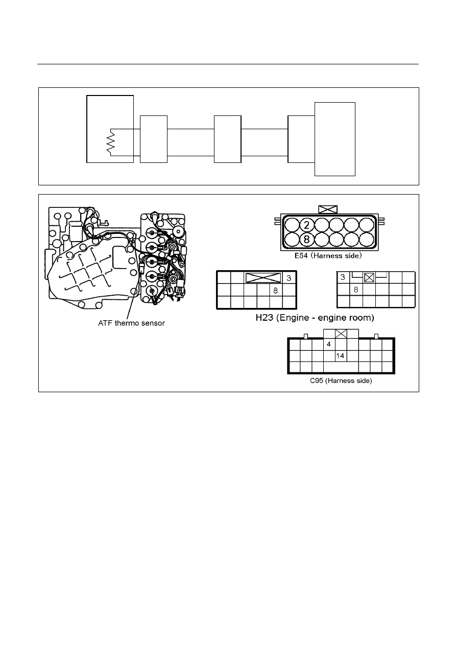
DTC P0710 (Flash Code 15) ATF Temperature Sensor Failure
ATF
Temp.
Sensor
TCM
B4 (+)
B14 (-)
H23
(8)
(3)
C95
(4)
(14)
BLU
Terminal
Assembly
BLU/BLK
E54
(2)
(8)
BLU
BLU/BLK
Setting Condition:
•
The condition in which the voltage of oil temperature sensor is below 0.1V (146
°
C) and ATF temperature
warning lamp ON in the P or N range lasts for more than 5 minutes.
Or
•
The vehicle speed exceeds 20 km/h and the voltage of oil temperature sensor exceeds 2.43V (-40
°
C) for more
than 10 seconds.
Fail Safe:
•
The lock-up is inhibited, and TCM is controlled ATF temperature 80
°
C condition as substitute.
•
When the engine speed is more than 470 rpm for 10 minuets, the lock-up and gear shift to 4th (over-drive) are
allowed.
Possible Cause:
•
Oil temperature sensor wire open circuit or short circuit.
•
Oil temperature sensor malfunction.
•
Power supply wire open circuit, short circuit to battery or short circuit to ground between oil temperature sensor
and TCM terminal B4 (C95).
•
Ground wire open circuit or short circuit to battery between oil temperature sensor terminal and TCM terminal
B14 (C95).

DIAGNOSIS 7A2-41
•
Poor connection of each connector.
Reference:
Following output voltage and resistance can be measured by circuit tester.
Measurement terminal: B4 (C95) and B14 (C95)
Temperature
Output Voltage (V)
Resistance
20
°
C
1.55
2,500
Ω
°
C
1.08
1,160
Ω
60
°
C
0.7
590
Ω

7A2-42 DIAGNOSIS
DTC P0560 (Flash Code 16) System Voltage Failure
TCM
A1 (+B)
B5
B15
H23
(15)
C95
(5)
(15)
BLK/YEL
BLK
BLK
Battery
C94
(1)
BLK
Setting Condition:
•
The supply voltage is below 10V and the engine speed exceeds 1000 rpm for more than 1 second.
Fail Safe:
•
When the vehicle is running, the gear position selected at the trouble detection is held and the lock-up is
inhibited.
•
After the vehicle stopped, all solenoid operations stop (OFF) and the gear is fixed to the 3rd. (In case of fail-safe
valve failure, gear shift to 4th (over-drive) is inhibited.)
Possible Cause:
•
Alternator or battery malfunction.
•
Power supply wire open circuit or short circuit to ground between power supply and TCM terminal A1 (C94).
•
Ground wire open circuit or short circuit to battery between ground location and TCM terminal B5 (C95) or B15
(C95).
•
Poor connection of each connector.
DIAGNOSIS 7A2-43
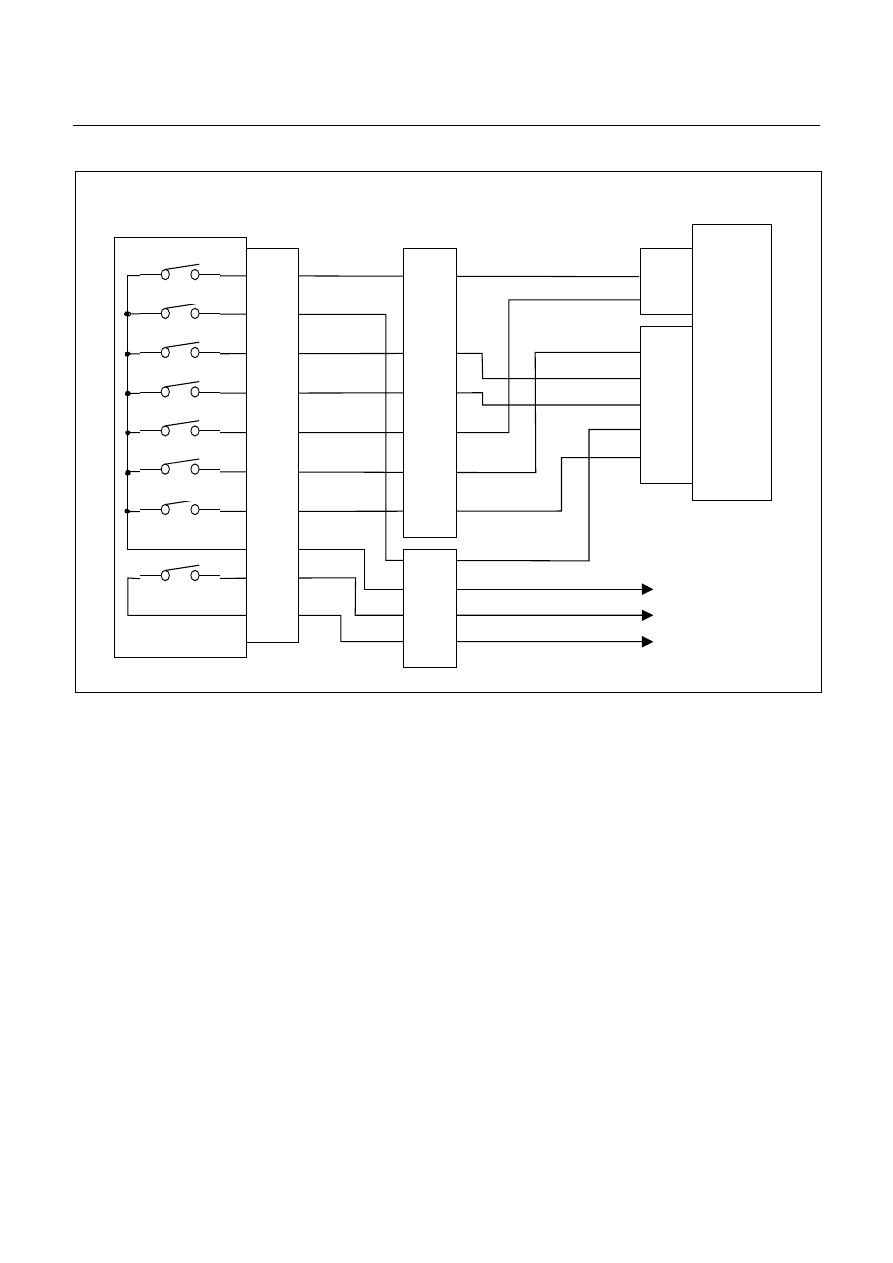
DTC P0705 (Flash Code 17) Inhibitor Switch Failure
Inhibitor SW
TCM
A2 (P)
A17 (3)
B2 (2)
B10 (N)
B11 (D)
B19 (R)
B21 (L)
C95
(2)
(10)
(11)
(19)
(21)
YEL/VIO
RED/BLK
BLU
BLK/GRN
Starter Relay
C94
(2)
(3)
B
H22
(1)
(6)
(4)
(7)
(5)
(2)
P
2
R
N
D
3
L
Start SW
PNK/BLU
E51
(2)
(4)
(8)
(5)
(1)
(9)
(6)
(3)
(10)
(7)
(38)
(15)
(3)
(37)
H4
PNK/BLK
RED/YEL
YEL/VIO
BLK/GRN
PNK/BLK
RED/BLK
BLU
RED/YEL
PNK/BLU
BLK/WHT
BLK
BLK
BLK/WHT
Key Switch
WHT
WHT
Immobiliser Control Unit
Нет комментариевНе стесняйтесь поделиться с нами вашим ценным мнением.
Текст