Isuzu D-Max / Isuzu Rodeo (TFR/TFS). Manual — part 1539
8-256 ELECTRICAL-BODY AND CHASSIS
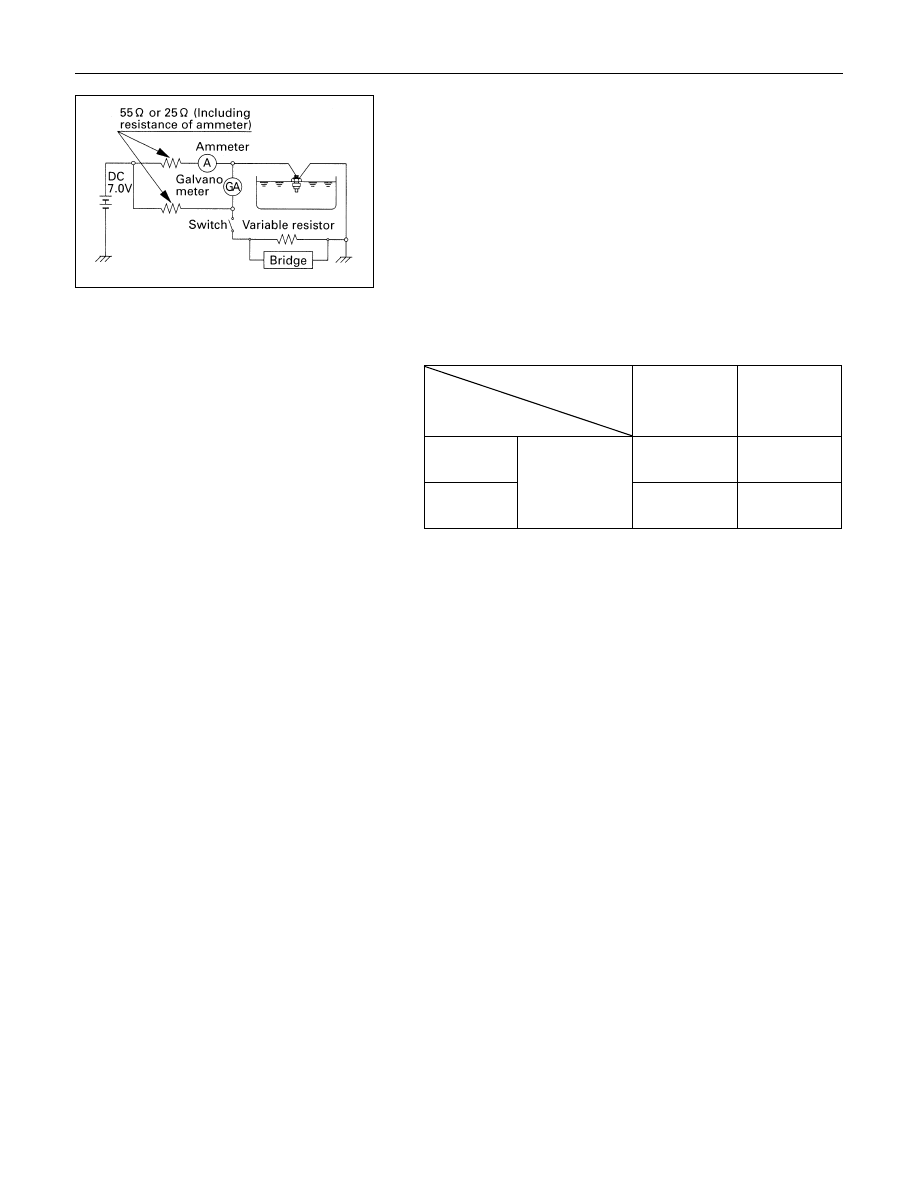
Thermo Unit Inspection
The thermo unit is thermistor type and must be inspected
under the conditions as shown in the left chart.
1. Put the deviation of the galvanometer to 0 by using the
variable resistor, switch the thermo unit off and then
measure the resistance of the resistor through the bridge.
Confirm that the resistance is continuously variable in any
other points than those shown in the following table.
2. Dip the thermo unit into 80 - 90
°C (176 - 194°F) water and
confirm that there is no bubble continuously coming out of
inside of the unit.
Replace the unit when the result of inspection is found
abnormal.
Temperature
Check
condition
50
°C
(122
°F)
115
°C
(239
°F)
7V 55
Ω
Gauge
Resistance
+33.6
226.0
-36.6
+1.71
26.4
-2.21
7V 25
Ω
Gauge
value (
Ω)
-
+2.68
24.3
-3.68

ELECTRICAL-BODY AND CHASSIS 8-257
FUEL GAUGE AND TANK UNIT
Fuel gauge On-Vehicle Inspection
1. Disconnect the fuel gauge wire connector.
2. Connect a 3.4 Watt test bulb
1
to the ground.
The gauge needle should more the middle part of the
gauge.
Fuel Gauge Off-Vehicle Inspection
Use a circuit tester to measure the fuel gauge resistance.
Fuel Gauge Resistance
Ω
Standard
Measuring Point
With
Tachometer
Without
Tachometer
IGN (+) - Ground
223
110
IGN (+) - 7V
(0)
IGN (+) - UNIT
83
25
Ground - 7V
110
Ground - UNIT
140
135
7V - UNIT
25
8-258 ELECTRICAL-BODY AND CHASSIS
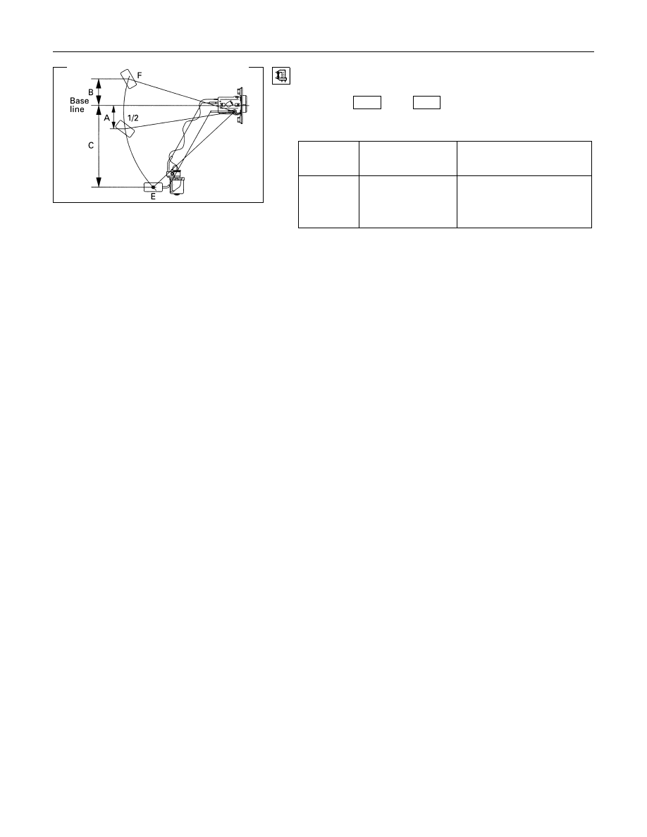
Fuel Tank Unit Inspection
Measure the fuel tank unit resistance between the connector
terminals 1
F-1
and 3
F-1
while shifting the float from “E”
to “F” point.
Fuel Tank Resistance
Level
Float position
mm
Standard resistance
Ω
F (B)
51.7
17
± 2.1
1/2 (A)
49.4
45
± 4.5
E (C)
166.9
120
± 6.5
ELECTRICAL-BODY AND CHASSIS 8-259
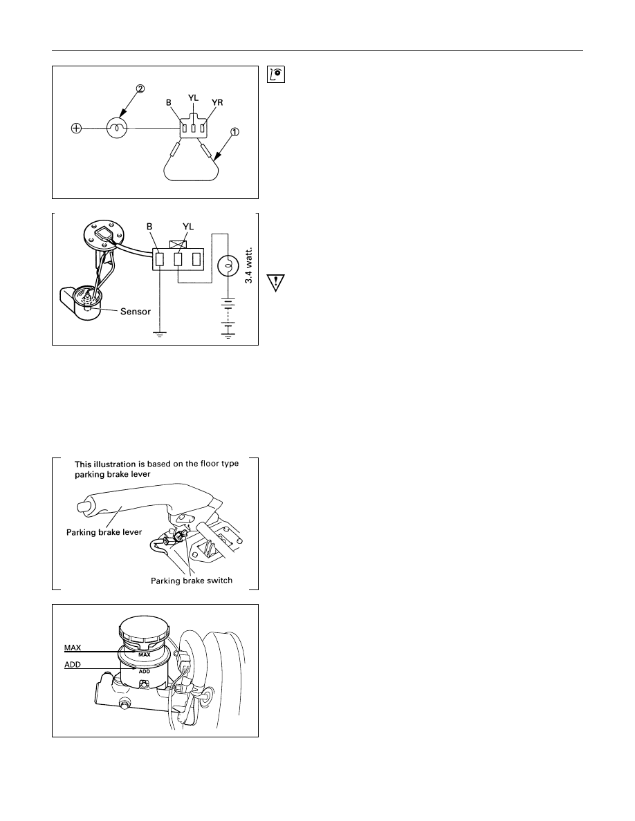
Low Fuel Indicator Light Inspection
1. Disconnect the fuel tank unit wire connector.
2. Connect between terminal (YL) and (B).
3. Turn the key switch on. Check that the bulb lights.
If operation is not correct, remove and check the bulb or circuit.
Check level sensor operation
1. Remove the fuel tank unit.
2. Apply battery voltage between terminal (YL) and (B) through
a 3.4 watt bulb. Check that the bulb lights.
Note:
It will take a short time for the bulb light.
3. Submerge the sensor in fuel. Check that the bulb goes out.
If operation is not correct, replace the fuel tank unit.
BRAKE SYSTEM WARNING LIGHT
The brake system warning light comes on while the parking
brake is set and the starter key is ON position.
Note:
The parking brake indicator light circuit is designed to
prevent driving of the vehicle with the parking brake on.
It does not indicate the condition of the parking brake
system.
The parking brake switch is in parallel with the brake fluid
switch.
The brake system warning light also comes on when reservoir
brake fluid level falls below the specified limit with the parking
brake released and the starter switch is ON position.
Нет комментариевНе стесняйтесь поделиться с нами вашим ценным мнением.
Текст