Isuzu D-Max / Isuzu Rodeo (TFR/TFS). Manual — part 834

6E–65
3.2L ENGINE DRIVEABILITY AND EMISSIONS
CAUTION: To reduce the risk of fire and personal
injury:
D
It is necessary to relieve fuel system pressure
before connecting a fuel pressure gauge. Refer to
Fuel Pressure Relief Procedure, below.
D
A small amount of fuel may be released when
disconnecting the fuel lines. Cover fuel line
fittings with a shop towel before disconnecting, to
catch any fuel that may leak out. Place the towel in
an approved container when the disconnect is
completed.
Fuel Pressure Relief Procedure
1. Remove the fuel cap.
2. Remove the fuel pump relay from the underhood
relay center.
3. Start the engine and allow it to stall.
4. Crank the engine for an additional 3 seconds.
Fuel Gauge Installation
1. Remove the shoulder fitting cap.
2. Install fuel gauge 5-8840-0378-0 to the fuel feed line
located in front of and above the right side valve
cover.
3. Reinstall the fuel pump relay.
Fuel System Electrical Test
Step
Action
Value(s)
Yes
No
1
Was the “On-Board Diagnostic (OBD) System Check”
performed?
—
Go to
Step 2
Go to
OBD
System
Check
2
1. Read the “Caution” above.
2. Relieve the fuel system pressure and install the fuel
pump pressure gauge to the test fitting.
3. Use a Tech 2 to command the fuel pump “ON.”
Is there an immediate pressure build-up which
indicates the pump is running?
—
Go to
Step 3
Go to
Step 4
3
1. Verify that the pump is not running by removing the
fuel filler cap and listening.
2. Command the pump “ON” with the Tech 2.
Did the pump turn “OFF” after 2 seconds?
—
Test
completed
Go to
Step 12
4
1. Ignition “OFF.”
2. Remove the fuel pump relay.
3. Using a test light connected to ground, probe the
battery feed to the relay.
Did the light illuminate?
—
Go to
Step 6
Go to
Step 5
5
Repair short or open battery feed to fuel pump relay.
Is the action complete?
—
Verify repair
—
6
1. Connect a test light between the two wires that
connect to the fuel pump relay pull-in coil.
2. Ignition “ON.”
Did the test light illuminate for 2 seconds and then turn
off?
—
Go to
Step 12
Go to
Step 7
7
1. With a test light connected to battery (–), probe the
fuel pump relay connector at the wire which runs
from the relay pull–in coil to the ECM.
2. Ignition “ON.”
Did the test light illuminate for 2 seconds and then turn
off?
—
Go to
Step 8
Go to
Step 9
8
Locate and repair open in the fuel pump relay ground
circuit.
Is the action complete?
—
Verify repair
—
6E–66
3.2L ENGINE DRIVEABILITY AND EMISSIONS
Fuel System Electrical Test
(Cont'd)
Step
No
Yes
Value(s)
Action
9
Check for short or open between the ECM and the fuel
pump relay.
Was a problem found?
—
Verify repair
Go to
Step 10
10
1. Check the fuel pump relay circuit for a poor terminal
connection at the ECM.
2. If a problem is found, replace terminal as necessary.
Was a problem found?
—
Verify repair
Go to
Step 11
11
Replace the ECM.
Is the action complete?
—
Verify repair
—
12
1. Reconnect the fuel pump relay.
2. Disconnect the fuel pump electrical connector at the
fuel tank.
3. Using a test light connected to ground, probe the
fuel pump feed wire (harness side).
4. Command the fuel pump “ON” with a Tech 2.
Did the light illuminate for 2 seconds?
—
Go to
Step 15
Go to
Step 13
13
1. Substitute a known good realy for the fuel pump
realy.
2. Leave the test light connected as in step 12.
3. Command the fuel pump “ON” with the Tech 2.
4. After this test, re-connect the known good relay in
its proper location.
Did the test light illuminate for 2 seconds when the fuel
pump was commanded “ON?”
—
Go to
Step 17
Go to
Step 14
14
Check for a short circuit, blown fuse or open circuit
between the relay and the fuel tank.
Is the action complete?
—
Verify repair
—
15
1. With the fuel pump electrical connector at the fuel
tank disconnected, connect a test light between the
feed wire and the ground wire (harness side).
2. Command the fuel pump “ON” with a Tech 2.
Did the test light illuminate for 2 seconds?
—
Go to
Step 18
Go to
Step 16
16
Repair the open circuit in the fuel pump ground wire.
Is the action complete?
—
Verify repair
—
17
Replace the fuel pump relay.
Is the action complete?
—
Verify repair
—
18
Replace the fuel pump.
Is the action complete?
—
Verify repair
—
6E–67
3.2L ENGINE DRIVEABILITY AND EMISSIONS
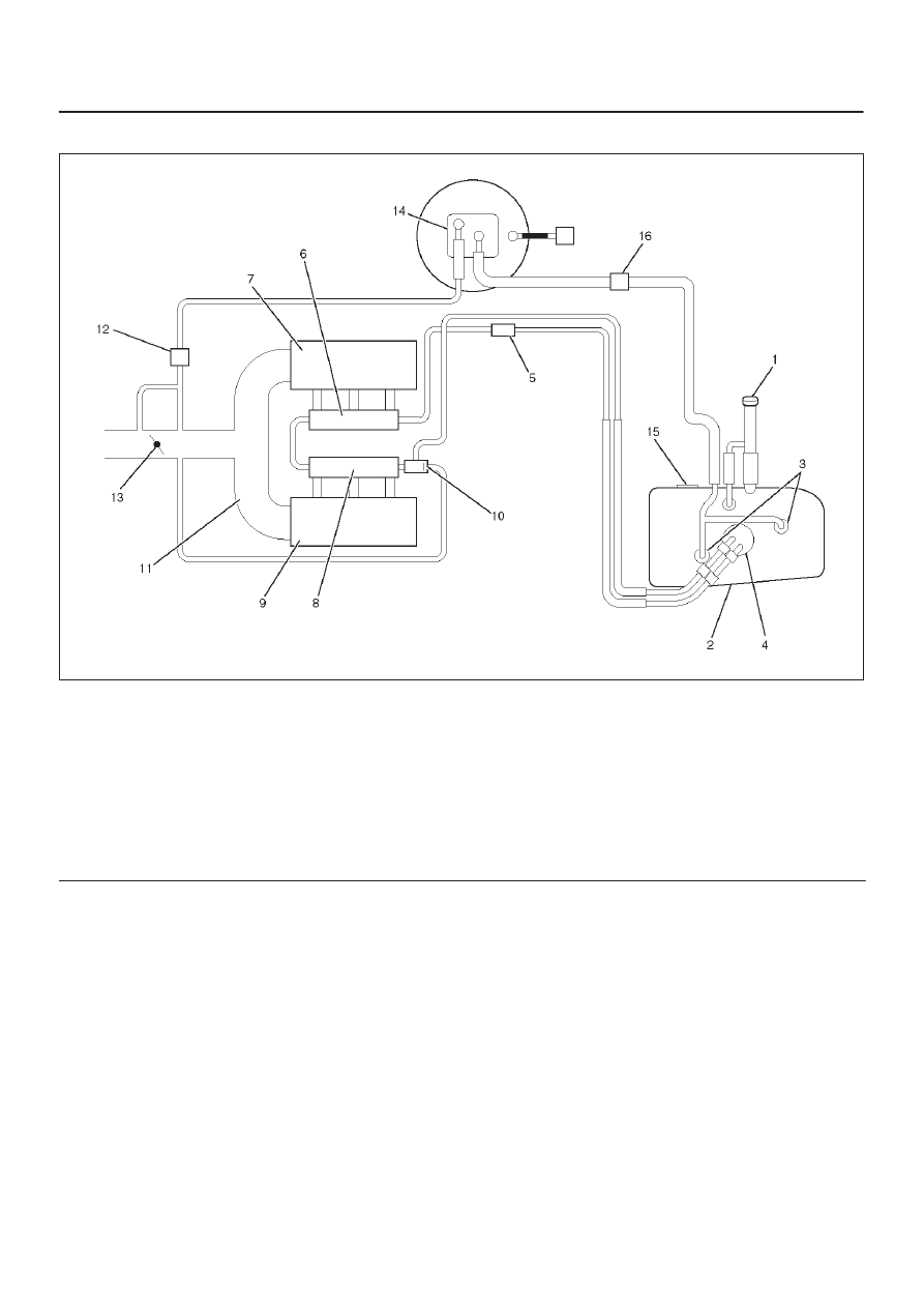
Fuel System Diagnosis
060RW245
Legend
(1) Fuel Filler Cap
(2) Fuel Tank
(3) Rollover Valve
(4) Fuel Pump Assembly
(5) Fuel Filter
(6) Fuel Rail Right
(7) Intake Air Port Right Bank
(8) Fuel Rail Left
(9) Intake Air Port Left Bank
(10) Fuel Pressure Control Valve
(11) Common Chamber
(12) Duty Solenoid Valve
(13) Throttle Valve
(14) Canister
(15) Fuel Gauge
(16) Check Valve
Circuit Description
When the ignition switch is turned “ON,” the Engine
Control Module ECM will turn “ON” the in-tank fuel pump.
The in-tank fuel pump will remain “ON” as long as the
engine is cranking or running and the ECM is receiving
58X crankshaft position pulses. If there are no 58X
crankshaft position pulses, the ECM will turn the in-tank
fuel pump “OFF” 2 seconds after the ignition switch is
turned “ON” or 2 seconds after the engine stops running.
The in-tank fuel pump is an electric pump within an
integral reservoir. The in-tank fuel pump supplies fuel
through an in-line fuel filter to the fuel rail assembly. The
fuel pump is designed to provide fuel at a pressure above
the pressure needed by the fuel injectors. A fuel pressure
regulator, attached to the fuel rail, keeps the fuel available
to the fuel injectors at a regulated pressure. Unused fuel
is returned to the fuel tank by a separate fuel return line.
Test Description
Number(s) below refer to the step number(s) on the
Diagnostic Chart.
2. Connect the fuel pressure gauge to the fuel feed line
as shown in the fuel system illustration. Wrap a
shop towel around the fuel pressure connection in
order to absorb any fuel leakage that may occur
when installing the fuel pressure gauge. With the
ignition switch “ON” and the fuel pump running, the
fuel pressure indicated by the fuel pressure gauge
should be 333-376 kpa (3.4-3.8 kg/cm
2
/ 48-55 psi).
This pressure is controlled by the amount of
pressure the spring inside the fuel pressure
regulator can provide.
3. A fuel system that cannot maintain a constant fuel
pressure has a leak in one or more of the following
areas:
D
The fuel pump check valve.
6E–68
3.2L ENGINE DRIVEABILITY AND EMISSIONS
D
The fuel pump flex line.
D
The valve or valve seat within the fuel pressure
regulator.
D
The fuel injector(s).
4. Fuel pressure that drops off during acceleration,
cruise, or hard cornering may case a lean condition.
A lean condition can cause a loss of power, surging,
or misfire. A lean condition can be diagnosed using
a Tech 1 Tech 2. If an extremely lean condition
occurs, the oxygen sensor(s) will stop toggling. The
oxygen sensor output voltage(s) will drop below 500
mV. Also, the fuel injector pulse width will increase.
IMPORTANT:
Make sure the fuel system is not
operating in the “Fuel Cut-Off Mode.”
When the engine is at idle, the manifold pressure is
low (high vacuum). This low pressure (high vacuum)
is applied to the fuel pressure regulator diaphragm.
The low pressure (high vacuum) will offset the
pressure being applied to the fuel pressure regulator
diaphragm by the spring inside the fuel pressure
regulator. When this happens, the result is lower fuel
pressure. The fuel pressure at idle will vary slightly as
the barometric pressure changes, but the fuel
pressure at idle should always be less than the fuel
pressure noted in step 2 with the engine “OFF.”
16.Check the spark plug associated with a particular
fuel injector for fouling or saturation in order to
determine if that particular fuel injector is leaking. If
checking the spark plug associated with a particular
fuel injector for fouling or saturation does not
determine that a particular fuel injector is leaking,
use the following procedure:
D
Remove the fuel rail, but leave the fuel lines and
injectors connected to the fuel rail. Refer to
Fuel Rail
Assembly in On-Vehicle Service.
D
Lift the fuel rail just enough to leave the fuel injector
nozzles in the fuel injector ports.
CAUTION: In order to reduce the risk of fire and
personal injury that may result from fuel spraying on
the engine, verify that the fuel rail is positioned over
the fuel injector ports and verify that the fuel injector
retaining clips are intact.
D
Pressurize the fuel system by connecting a 10 amp
fused jumper between B+ and the fuel pump relay
connector.
D
Visually and physically inspect the fuel injector
nozzles for leaks.
17.A rich condition may result from the fuel pressure
being above 376 kpa (55 psi). A rich condition may
cause a DTC P0132 or a DTC P0172 to set.
Driveability conditions associated with rich
conditions can include hard starting (followed by
black smoke) and a strong sulfur smell in the
exhaust.
20.This test determines if the high fuel pressure is due
to a restricted fuel return line or if the high fuel
pressure is due to a faulty fuel pressure regulator.
21.A lean condition may result from fuel pressure
below 333 kpa (48 psi). A lean condition may cause
a DTC P0131 or a DTC P0171 to set. Driveability
conditions associated with lean conditions can
include hard starting (when the engine is cold ),
hesitation, poor driveability, lack of power, surging ,
and misfiring.
22.Restricting the fuel return line causes the fuel
pressure to rise above the regulated fuel pressure.
Command the fuel pump “ON” with the Tech 2. The
fuel pressure should rise above 376 kpa (55 psi) as
the fuel return line becomes partially closed.
NOTE: Do not allow the fuel pressure to exceed 414 kpa
(60 psi). Fuel pressure in excess of 414 kpa (60 psi) may
damage the fuel pressure regulator.
CAUTION: To reduce the risk of fire and personal
injury:
D
It is necessary to relieve fuel system pressure
before connecting a fuel pressure gauge. Refer to
Fuel Pressure Relief Procedure, below.
D
A small amount of fuel may be released when
disconnecting the fuel lines. Cover fuel line
fittings with a shop towel before disconnecting, to
catch any fuel that may leak out. Place the towel in
an approved container when the disconnect is
completed.
Fuel Pressure Relief Procedure
1. Remove the fuel cap.
2. Remove the fuel pump relay from the underhood
relay center.
3. Start the engine and allow it to stall.
4. Crank the engine for an additional 3 seconds.
Fuel Gauge Installation
1. Remove the shoulder fitting cap.
2. Install fuel gauge 5-8840-0378-0 to the fuel supply
line located in front of and above the right side valve
cover.
3. Reinstall the fuel pump relay.
Нет комментариевНе стесняйтесь поделиться с нами вашим ценным мнением.
Текст