Isuzu D-Max / Isuzu Rodeo (TFR/TFS). Manual — part 1686
6A-42 ENGINE MECHANICAL (C24SE, C22NE, 22LE, 20LE)
Hydraulic Valve Lifters, Replace
Removal
1.
Remove the spark plug connectors and spark plugs.
2.
Remove the camshaft housing cover.
Removal
3.
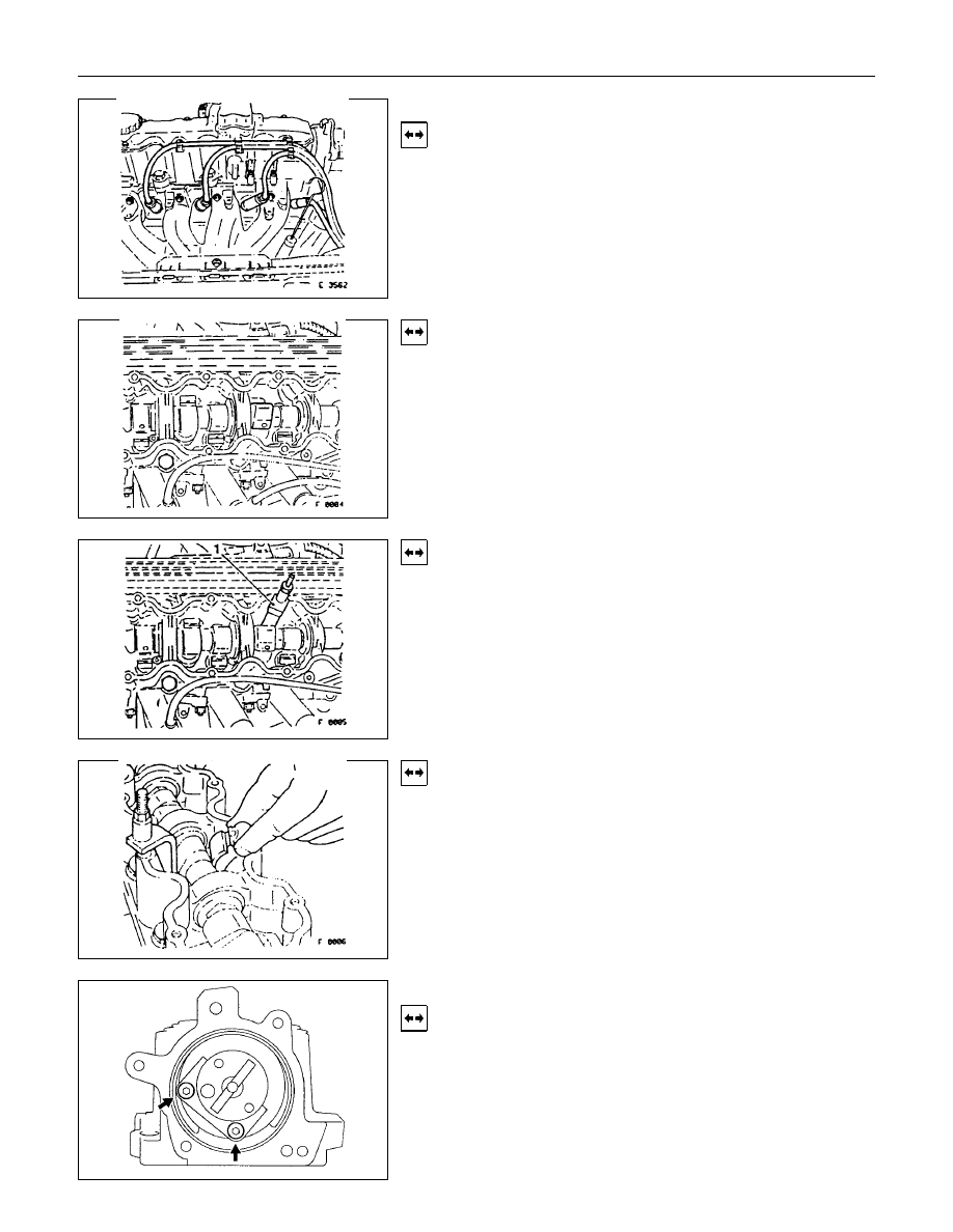
Turn the crankshaft at fastening bolt of toothed belt drive
gear in the direction of the engine rotation until the cam
of hydraulic valve lifter being replaced stands vertically.
Removal
4.
Apply 5-8840-0457-0 to the camshaft housing, valve
spring cap and tension valve spring.
Removal
5.
Remove the cam follower from camshaft housing.
Note thrust pieces.
6.
Remove hydraulic valve lifter from camshaft housing.
Camshaft Housing, Replace
Removal
Cylinder head-see operation “Cylinder Head. Remove and
Install”.

ENGINE MECHANICAL (C24SE, C22NE, 22LE, 20LE) 6A-43
Inspection
All parts, if necessary replace.
When replacing camshaft, always replace all cam followers.
Installation
Insert hydraulic valve lifter (1) in camshaft housing.
Coat sliding surfaces of rocker arm with Mcs, Paste and insert
in camshaft housing.
Adjust
Adjustment of the hydraulic valve liters is not required.
Pretension is provided by the design.
Installation
1.
Remove 5-8840-0457-0 and install the camshaft housing
cover.
2.
Insert the spark plug connectors.
Tighten (Torque)
Guide plate to camshaft housing.
Insert camshaft with MoS
2
paste.
Installation
1.
Install the front seal ring in camshaft housing with
5-8840-0451-0.
2.
Install the camshaft housing rear cover.
3.
Install the cylinder head.
6A-44 ENGINE MECHANICAL (C24SE, C22NE, 22LE, 20LE)
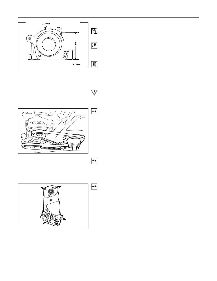
Camshaft Housing, Check for Plane Surface
Clean
Sealing surfaces.
Inspection
Check length and width of sealing surface for deformation and
diagnosis for warpage and use straight edge feeler gauge.
Measure
Height of camshaft housing (sealing surface to sealing
surface).
Dimension I: (74.0 mm)
Cylinder Head, Removal and Installation
Important
Only remove cylinder head with engine cold (room
temperature).
Removal
1.
Remove the alternator, power steering and V-belts.
Removal
2.
Loosen the fastening bolts from alternator.
3.
Loosen the lower alternator fastening bolt by swinging the
alternator to the rear.
Removal
4.
Remove the front toothed belt cover.
5.
Remove the toothed belt from camshaft pulley.
See operation "Timing Check and Adjust".
ENGINE MECHANICAL (C24SE, C22NE, 22LE, 20LE) 6A-45
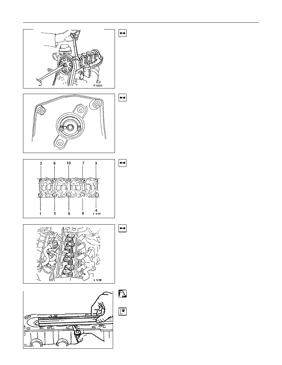
Removal
6.
Remove the camshaft housing cover and camshaft pulley
by counter-holding at the hex head of camshaft.
Removal
7.
Remove the fastening bolts from camshaft housing.
Removal
8.
Remove the exhaust pipe from exhaust manifold.
9.
Loosen the cylinder head bolts spirally from the outside
inwards (first 1/4, then 1/2 revolution).
Removal
1.
Remove the camshaft housing from cylinder head.
2.
Remove the cam followers, thrust pieces and hydraulic
valve lifters.
Note the allocation.
3.
Remove the cylinder head.
Clean
Sealing surfaces, bores and threads of cylinder head bolts.
Inspection
Check cylinder head and cylinder block for plane surfface-see
operations “Cylinder Head, Check for Plane Surface” and
“Cylinder Block, Check for Plane Surface.”
Нет комментариевНе стесняйтесь поделиться с нами вашим ценным мнением.
Текст