Isuzu D-Max / Isuzu Rodeo (TFR/TFS). Manual — part 986
BRAKES 5-15
SERVICING
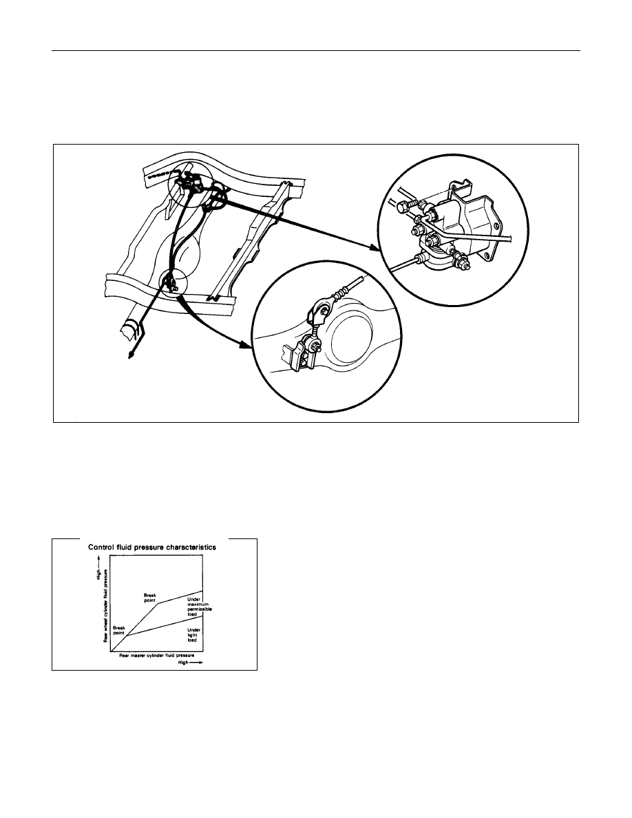
LOAD SENSING PROPORTIONING VALVE (LSPV)
Location of LSPV
Structure and Operation
The following is an explanation of the structure and operation
of the linkage type load sensing device.
This device controls the fluid pressure to the rear brakes in
accordance with changes in rear axle load (vertical
displacements of the rear axle springs).
•
Structure
This device consists of a load sensing spring (bending bar)
and a valve.
The valve is mounted through a bracket to the frame.
One end of the load sensing spring is fixed to the valve at
the frame and the other end to the rear axle housing
through a shackle.

5-16 BRAKES
From
primary
master cylinder
From
Secondary
master cylinder
•
Operation
1) Outline
When the L.S.P.V.(Load Sensing Proportioning Valve)
detects a change in load weight, the load sensing spring
deflects.
Its reaction force is transmitted to the bottom of the load
sensing valve to secure an optimum rear wheel cylinder
fluid pressure break point in proportion to the actual load
weight.
Besides, if the front brake system should fail, the device is
designed to prevent the master cylinder fluid pressure from
decreasing and to apply it directly to the rear wheel cylinder
to obtain a sufficient braking performance.
Primary master
cylinder fluid
pressure
Secondary master
cylinder fluid
pressure
2) Operation
(1) When the fluid pressure is under the break point.
The fluid pressure of the rear master cylinder passes
through a clearance between the valve seal and the piston
and acts on the rear wheel cylinder.
At this moment, a downward force is applied to the piston.
However, the compression spring force and reaction force
of the load sensing spring keep the piston in the upper
position by pushing upwards. (See the left figure.)
Primary master
cylinder fluid
pressure
Secondary master
cylinder fluid
pressure
(2) When the fluid pressure is equal to the break point.
As the rear wheel cylinder pressure increases, it surpasses
the compression spring force and reaction force of the load
sensing spring, causing the piston to move downwards, so
that the piston butts against the valve seal to shut off the
fluid line between the master cylinder and rear wheel
cylinder. (See the left figure.)
(3) When the fluid pressure is over the break point.
When the fluid pressure increases further, the piston moves
upwards.
The moment the piston comes apart from the valve seal,
fluid pressure is applied to the rear wheel cylinder and the
piston moves downwards so that the fluid line is shut off
again.
This process goes on repeatedly to control the fluid
pressure to the rear wheel cylinder.

BRAKES 5-17
Secondary master
cylinder fluid
pressure
(4) When the front brake system fails.
When there is a failure in the front brake system, the fluid
pressure from the front master cylinder decreases.
As a result, the balance between the front and rear brake
side fluid pressures are lost at the control valve sleeve so
that the control valve sleeve moves upwards.
The control valve sleeve strikes against the piston, thereby
pushing the piston upwards.
Accordingly, the fluid pressure of the rear mater cylinder is
not decreased and is applied directly to the rear wheel
cylinder to secure a sufficient braking performance of the
rear brakes. (See the left figure.)
Valve Maintenance
In the case of fluid lead or other a abnormalities, faulty valve
should be replaced.
Note:
The load sensing proportioning valve is not repairable and
must be replaced as a completed assembly.
ADJUSTMENT PROCEDURE OF LSPV
This adjustment should be performed with the battery voltage
applied to the valve.
1. Adjust the rear axle weight by loading the rear body as
necessary.
Rear axle weight
kg (lbs)
TFR
750(1.654)
TFS
900(1.985)
Note:
The rear axle weight should be adjusted to the specified
value with a man seated in the driver seat.

5-18 BRAKES
2. Connect the wiring with miniature lamp (1) and a battery (2)
between valve bracket (3) and linkage (4) with each end of
wiring clipped.
This wiring is necessary to find the moment at which piston
within the valve assembly is brought into connect with the
linkage.
Note:
As the linkage is coated with insulation material, turn the
clip (5) with 2 or 3 turns to break insulation.
3. Loosen the nut (6) and raise the valve assembly (7) all the
way.
Then lower the valve assembly gradually and tighten the nut
(6) when miniature lamp (1) turns on.
Torque
N
⋅
m(kgf
⋅
m/lb
⋅
ft)
17(1.7/12)
Note:
If the miniature lamp (1) goes out as the nut (6) is
tightened, lower the valve assembly (7) slightly with the
nut loosened, then retighten the nut(6).
4. Depress the linkage (4) near the valve assembly slightly
downward with finger (test pressue:0.5-0.8kg) and check to
see if the miniature lamp (1) goes out.
Lamp goes out
: OK Adjustment is completed.
Lamp remains on : NG Repeat
adjustment
operation
outline under paragraph 3.
Excessive force is exerted on
linkage by piston (8) within the
valve assembly.
Note:
Adjustment can also be made by means of nuts (9) and
(10) on shackle at rear axle case side.
However, shackle nut is not normally used for adjustment
as it is for making fine adjustment.
Нет комментариевНе стесняйтесь поделиться с нами вашим ценным мнением.
Текст