Isuzu D-Max / Isuzu Rodeo (TFR/TFS). Manual — part 141
6E–168
4JH1 ENGINE DRIVEABILITY AND EMISSIONS
DIAGNOSTIC TROUBLE CODE (DTC) P0400 (SYMPTOM CODE 3)
(FLASH CODE 32) EXHAUST GAS RECIRCULATION FLOW EXCESSIVE
DETECTED
DIAGNOSTIC TROUBLE CODE (DTC) P0400 (SYMPTOM CODE 4)
(FLASH CODE 32) EXHAUST GAS RECIRCULATION CIRCUIT SHORT TO
GROUND OR OPEN CIRCUIT
DIAGNOSTIC TROUBLE CODE (DTC) P0400 (SYMPTOM CODE 5)
(FLASH CODE 32) EXHAUST GAS RECIRCULATION FLOW INSUFFICIENT
DETECTED
DIAGNOSTIC TROUBLE CODE (DTC) P0400 (SYMPTOM CODE 8)
(FLASH CODE 32) EXHAUST GAS RECIRCULATION CIRCUIT SHORT TO
BATTERY
Batt
µP
0.5
BLK/
URG
0.5
BLU/
RED
0.5
BLU/
RED
97
0.5
WHT/
RED
83
0.5
GRN/
RED
88
0.5
BLK/
RED
92
0.5
BLK/
BLU
84
IAT
Sensor
MAF &
IAT
Sensor
ECM
10A
EGR-
EVRV
2
4
5
3
1
ECM
Main Relay
IC
IC
CPU
Engine
Control
Module
(ECM)

4JH1 ENGINE DRIVEABILITY AND EMISSIONS
6E–169
Condition for setting the DTC and action taken when the DTC sets
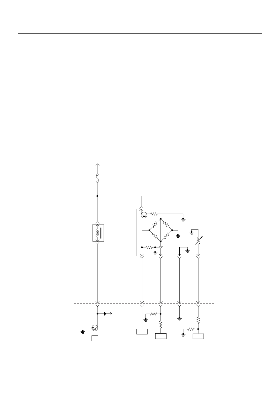
Circuit Description
The amount of EGR is controlled by EVRV (electrical
vacuum regulating valve) via the engine control module
(ECM) command signal depends on the engine speed,
operating of the accelerator pedal and engine coolant
temperature.
The EVRV is shaped to control vacuum applied to the
diaphragm chamber of the EGR valve based on duty
signal sent from the ECM.
If the EGR valve is stuck at open position or close
position, DTC P0400 (Symptom Code 3) or DTC P0400
(Symptom Code 5) is stored.
If the EGR EVRV circuit is open or short ground circuit,
DTC P0400 (Symptom Code 4) is stored.
If the EGR EVRV circuit is short to voltage circuit, DTC
P0400 (Symptom Code 8) is stored.
Diagnostic Aids
An intermittent may be caused by the following:
• Poor connections.
• Misrouted harness.
• Rubbed through wire insulation.
• Broken wire inside the insulation.
• EGR valve sticking.
• Faulty intake air duct connection.
Check for the following conditions:
• Poor connection at ECM-Inspect harness connectors
for backed out terminals, improper mating, broken
locks, improperly formed or damaged terminals, and
poor terminal to wire connection.
• Damaged harness-Inspect the wiring harness for
damage. If the harness appears to be OK, observe
the DTC P0400 display on the Tech2 while moving
connectors and wiring harnesses. A change in the
display will indicate the location of the fault.
Diagnostic Trouble Code (DTC) P0400 (Symptom Code 3) (Flash Code 32)
Exhaust Gas Recirculation Flow Excessive Detected
Flash
Code
Code
Symptom
Code
MIL
DTC Name
DTC Setting Condition
Fail-Safe (Back Up)
32
P0400
3
ON
Exhaust Gas Recirculation
Flow Excessive Detected
1. Intake air temperature is
between 15°C and 100°C.
2. Engine coolant temperature
is between 35°C and
100°C.
3. Barometric pressure is
between 850hpa and
1100hpa.
4. Small amount of mass air
flow. (Desired mass air flow
- mass air flow is more than
150mg/strk)
Fuel injection quantity is
reduced.
4
ON
Exhaust Gas Recirculation
Circuit Short to Ground or
Open Circuit
EGR EVRV circuit open or
short to ground circuit.
Fuel injection quantity is
reduced and EGR EVRV 10%
conditions as substitute.
5
ON
Exhaust Gas Recirculation
Flow Insufficient Detected
1. Intake air temperature is
between 15°C and 100°C.
2. Engine coolant temperature
is between 35°C and
100°C.
3. Barometric pressure is
between 850hpa and
1100hpa.
4. Large mount of mass air
flow. (Desired mass air
flow - mass air flow is below
150 mg/strk)
Fuel injection quantity is
reduced.
8
ON
Exhaust Gas Recirculation
Circuit Short to Battery
EGR EVRV circuit short to
voltage circuit.
Fuel injection quantity is
reduced & EGR EVRV 10%
conditions as substitute.
Step
Action
Value(s)
Yes
No
1
Was the “On-Board Diagnostic (OBD) System Check”
performed?
—
Go to Step 2
Go to On Board
Diagnostic
(OBD) System
Check

6E–170
4JH1 ENGINE DRIVEABILITY AND EMISSIONS
2
1. Connect the Tech 2.
2. Review and record the failure information.
3. Select “F0: Read DTC Infor As Stored By ECU” in
“F0: Diagnostic Trouble Codes”.
Is the DTC P0400 (Symptom Code 3) stored as
“Present Failure”?
—
Go to Step 3
Refer to
Diagnostic Aids
and Go to Step
3
3
1. Using the Tech 2, ignition “On” and engine “Off”.
2. Select “F1: Clear DTC Information” in “F0:
Diagnostic Trouble Codes” with the Tech 2 and
clear the DTC information.
3. Operate the vehicle and monitor the “F0: Read
DTC Infor As Stored By ECU” in the “F0:
Diagnostic Trouble Codes”.
Was the DTC P0400 (Symptom Code 3) stored in this
ignition cycle?
—
Go to Step 4
Refer to
Diagnostic Aids
and Go to Step
4
4
Remove the MAF & IAT sensor assembly and check
for the following conditions.
• Objects blocking the air cleaner.
• Objects blocking the MAF sensor.
• Vacuum leaking at intake duct.
• Objects blocking the turbocharger.
If a problem is found, repair as necessary.
Was the problem found?
—
Verify repair
Go to Step 5
5
Remove the MAF & IAT sensor assembly and visually
check.
Was the problem found?
—
Go to Step 6
Go to Step 8
6
Substitute a known good MAF & IAT sensor assembly
and recheck.
Was the problem solved?
—
Go to Step 7
Go to Step 8
7
Replace the MAF & IAT sensor assembly.
Is the action complete?
—
Verify repair
—
8
Using the DVM and check the EGR EVRV.
1. Ignition “Off”, engine “Off”.
2. Disconnect the EGR EVRV connector.
3. Measure the resistance of EGR EVRV solenoid
coil.
Does the tester indicate standard resistance?
Approximately
14
Ω at 20°C
Go to Step 11
Go to Step 9
9
Substitute a known good EGR EVRV and recheck.
Was the problem solved?
—
Go to Step 10
Go to Step 11
10
Replace the EGR EVRV.
Is the action complete?
—
Verify repair
—
Step
Action
Value(s)
Yes
No
1
2
EGR EVRV
1
2
4JH1 ENGINE DRIVEABILITY AND EMISSIONS
6E–171
11
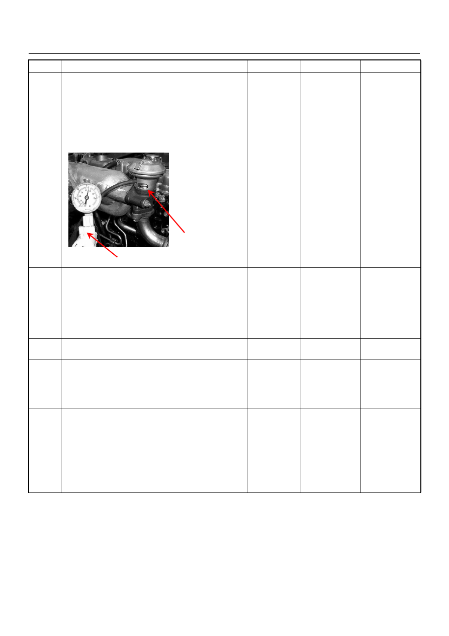
Using the vacuum pump and check the EGR valve
operation for the following condition through the small
window.
• Restrict shaft movement. Check for objects sticking
the shaft, broken diaphragm or excessive carbon
deposit.
If a problem is found, repair as necessary.
Was a problem found?
—
Verify repair or
Go to Step 13
Go to Step 12
12
Inspect the EGR valve.
1. Remove the EGR valve from the engine.
2. Inspect the EGR valve whether pintle valve is
stuck or damaged.
If excessive carbon deposit is found, clean up the
EGR valve and inspect damage of the pintle and seat.
Was the problem found?
—
Verify repair or
Go to Step 13
Go to Step 14
13
Replace the EGR valve.
Is the action complete?
—
Verify repair
—
14
Is the ECM programmed with the latest software
release?
If not, download the latest software to the ECM using
the “SPS (Service Programming System)”.
Was the problem solved?
—
Verify repair
Go to Step 15
15
Replace the ECM.
Is the action complete?
IMPORTANT: The replacement ECM must be
programmed. Refer to section of the Service
Programming System (SPS) in this manual.
Following ECM programming, the immobiliser system
(if equipped) must be linked to the ECM. Refer to
section 11 “Immobiliser System-ECM replacement” for
the ECM/Immobiliser linking procedure.
—
Verify repair
—
Step
Action
Value(s)
Yes
No
Vacuum Pump
Small Window
Нет комментариевНе стесняйтесь поделиться с нами вашим ценным мнением.
Текст