Isuzu D-Max / Isuzu Rodeo (TFR/TFS). Manual — part 1997

STEERING 3B-67
DISASSEMBLY AND REASSEMBLY (6VD1 Engine Model)
Disassembly Steps
1. Bolt
2. Pipe, suction
3. O-ring
4. Connector
5. O-ring
6. Valve
7. Retaining ring
8. Filter
9. Spring
10. Pressure switch
11. Retaining ring
12. Shaft assembly
13. Bearing
14. Shaft
15. Retaining ring
16. Oil seal
17. Bolt
18. Rear housing assembly and pump
cartridge
19. Gasket
20. O-ring
21. O-ring
22. Front housing
23. Pressure plate
24. Rotor and vane
25. Cam
26. Pin
27. Rear housing
Reassembly Steps
27. Rear housing
26. Pin
25. Cam
24. Rotor and vane
23. Pressure plate
22. Front housing
21. O-ring
20. O-ring
19. Gasket
18. Rear housing assembly and pump
cartridge
17. Bolt
16. Oil seal
15. Retaining ring
14. Shaft
13. Bearing
12. Shaft assembly
11. Retaining ring
10. Pressure switch
9. Spring
8. Filter
7. Retaining ring
6. Valve
5. O-ring
4. Connector
3. O-ring
2. Pipe, suction
1. Bolt
3B-68 STEERING
DISASSEMBLY
Preparation:
Clean oil pump with solvent (its plug discharge and suction port
to prevent the entry of solvent). Be careful not to expose the oil
seal of shaft assembly to solvent.
1. Bolt
2. Pipe, Suction
3. O-ring
4. Connector
5. O-ring
6. Valve
7. Retaining Ring
8. Filter
9. Spring
10. Pressure Switch
11. Retaining Ring
12. Shaft Assembly
13. Bearing
14. Shaft
15. Retaining Ring
16. Oil Seal
CAUTION:
When removing the oil seal, be careful not to damage the
housing.
17. Bolt
18. Rear Housing Assembly and Pump Cartridge
19. Gasket
20. O-ring
21. O-ring
22. Front Housing
23. Pressure Plate
24. Rotor and Vane
25. Cam
26. Pin
27. Rear Housing
INSPECTION AND REPAIR
Make all necessary adjustments, repairs, and part
replacements if wear, damage, or other problems are
discovered during inspection.
STEERING 3B-69
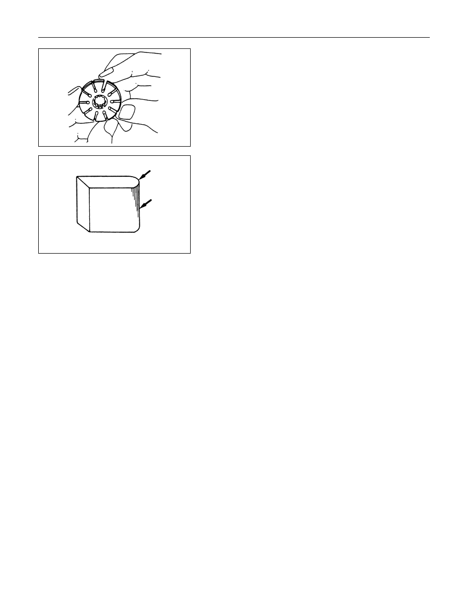
Rotor
Check that the groove in the vane is free from excessive wear
and that the vane slides smoothly
When part replacement becomes necessary, the pump
cartridge should be replaced as a subassembly.
Vane
Sliding faces of the vane should be free from wear.
(Particularly the curved face at the tip in contact with the cam
should be free from wear and distortion.)
When part replacement becomes necessary, the pump
cartridge should be replaced as a subassembly.
Cam
The inner face of the cam should have a trace of uniform
contact without a sign of step wear.
When part replacement becomes necessary, the pump
cartridge should be replaced as a subassembly.
Side plate
The sliding faces of parts must be free from step wear (more
than 0.01 mm), which can be felt by the finger nail.
The parts with minor scores may be reused after lapping the
face.
Valve
The sliding face of the valve must be free from burrs and
damage.
The parts with minor scores may be reused after smoothing
with emery cloth (#800 or finer).
Shaft
Oil seal sliding faces must be free from a step wear which can
be felt by the finger nail.
Needle bearing fitting face must be free from disintegration and
wear.
O-ring, oil seal retaining ring
Be sure to discard used parts, and always use new parts for
installation. Prior to installation, lubricate all seals and rings
with power steering fluid.
3B-70 STEERING
REASSEMBLY
27. Rear Housing
26. Pin
25. Cam
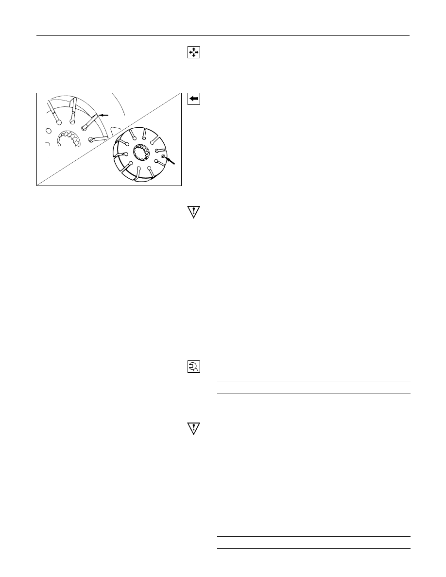
24. Rotor and Vane
1. Install the rotor with its punch mark facing the front
housing.
2. Install the vanes with curved face in contact with the
inner wall of the cam.
23. Pressure plate
CAUTION:
When install pressure plate, be careful not to damage its
inner surface. Damaged pressure plate may cause poor
pump performance, pump seizure or oil leakage.
22. Front Housing
21. O-ring
Be sure to discard used parts, and always used new parts
for installation.
20. O-ring
Be sure to discard used parts, and always used new parts
for installation.
19. Gasket
Be sure to discard used parts, and always used new parts
for installation.
18. Rear Housing Assembly and Pump Cartridge
17. Bolt
Rear Housing Bolt Torque
N
⋅m (kgf⋅m / lb⋅ft)
17.6 (1.8 / 12.8)
16. Oil Seal
Be sure to discard used parts, and always used new parts
for installation.
CAUTION:
When installing the oil seal, be careful not to damage the
oil seal contacting surface of the housing.
15. Retaining Ring
14. Shaft
13. Bearing
12. Shaft Assembly
11. Retaining Ring
10. Pressure Switch
Pressure Switch Torque
N
⋅m (kgf⋅m / lb⋅ft)
20 (2.0 / 14)
9. Spring
Нет комментариевНе стесняйтесь поделиться с нами вашим ценным мнением.
Текст