Isuzu D-Max / Isuzu Rodeo (TFR/TFS). Manual — part 1709

ENGINE ELECTRICAL 6D1-5
Battery fluid is a highly corrosive acid.
Should battery fluid come in contact with your eyes, skin, fabric,
or a painted surface, immediately and thoroughly rinse the
affected area with clean tap water.
Never allow metal tools or jumper cables to come in contact
with the positive battery terminal, or any other metal surface of
the vahicle. This will protect against a short circuit.
Always keep batteries out of reach of young children.
Jump Starting Procedure
1. Set the vehicle parking brake.
If the vahicle is equipped with an automatic transmission,
place the selector level in the "PARK" position.
If the vehicle is equipped with a manual transmission, place
the shift lever in the "NEUTRAL" position.
Turn "OFF" the ignition.
Turn "OFF" all lights and any other accessory requiring
electrical power.
2. Look at the built-in hydrometer.
If the indication area of the built-in hydrometer is completely
clear, do not try to jump start.
3. Attach the end of one jumper cable to the positive terminal
of the booster battery.
Attach the other end of the same cable to the positive
terminal of the discharged battery.
Do not allow the vehicles to touch each other. This will
cause a ground connection, effectively neutralizing the
charging procedure.
Be sure that the booster battery has a 12 volt rating.
4. Attach one end of the remaining cable to the negative
terminal of the booster battery.
Attach the other end of the same cable to a solid engine
ground (such as the air conditioning compressor bracket or
the generator mounting bracket) of the vehicle with the
discharged battery.
The ground connection must be at least 450 mm (18 in.)
from the battery of the vehicle whose battery is being
charged.
WARNING: NEVER ATTACH THE END OF THE JUMPER
CABLE DIRECTLY TO THE NEGATIVE TERMINAL OF THE
DEAD BATTERY.
5. Start the engine of the vehicle with the good battery.
Make sure that all unnecessary electrical accessories have
been turned "OFF".
6. Start the engine of the vehicle with the dead battery.
7. To remove the jumper cables, follow the above directions in
reverse order.
Be sure to first disconnect the negative cable from the
vehicle with the discharged battery.
6D1-6 ENGINE ELECTRICAL
1
5
3
4
2
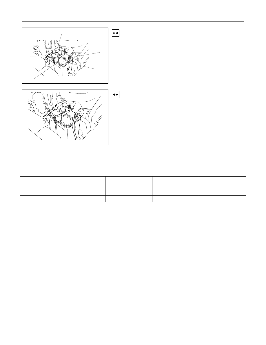
Removal
1. Remove negative cable (1).
2. Remove positive cable (2).
3. Remove retainer screw and rods (3).
4. Remove retainer (4).
5. Remove battery (5).
Installation
1. Install battery.
2. Install retainer.
3. Instal retainer screw and rods.
NOTE: Make sure that the rod is hooked on the body side.
4. Install positive cable.
5. Install negative cable.
Main Data and Specifications
General Specifications
Model (JIS)34B19L
46B19L
50D20L
Voltage (V)12
12
12
Cold Cranking Performance (Amp)272
325
306
Reserve Capacity (Min)49
71
78
IGNITION SYSTEM 6D2-1
SECTION 6D2
IGNITION SYSTEM
CONTENTS
PAGE
General Description . . . . . . . . . . . . . . . . . . . . . . . . . ... 6D2- 2
Service Precaution . . . . . . . . . . . . . . . . . . . . . . . . . . . 6D2- 2
Diagnosis . . . . . . . . . . . . . . . . . . . . . . . . . . . . . . 6D2- 2
Ignition Coil. . . . . . . . . . . . . . . . . . . . . . . . . . . . . . 6D2- 2
Removal. . . . . . . . . . . . . . . . . . . . . . . . . . . . . .. 6D2- 2
Installation. . . . . . . . . . . . . . . . . . . . . . . . . . . . .. 6D2- 2
Spark Plug. . . . . . . . . . . . . . . . . . . . . . . . . . . . . ... 6D2- 3
Removal. . . . . . . . . . . . . . . . . . . . . . . . . . . . . .. 6D2- 3
Inspection and Repair . . . . . . . . . . . . . . . . . . . . . . . ... 6D2- 3
Installation. . . . . . . . . . . . . . . . . . . . . . . . . . . . .. 6D2- 4
Crankshaft Angle Sensor. . . . . . . . . . . . . . . . . . . . . . . ... 6D2- 4
Removal. . . . . . . . . . . . . . . . . . . . . . . . . . . . . .. 6D2- 4
Installation. . . . . . . . . . . . . . . . . . . . . . . . . . . . .. 6D2- 4
Main Data and Specifications. . . . . . . . . . . . . . . . . . . . . . 6D2- 5
6D2-2 IGNITION SYSTEM
General Description
Ignition is done by the Ignition Module that fires.
Since the cylinder on exhaust stroke requires less energy to
fire its spark plug, energy from the ignition coils can be utilized
to fire the mating cylinder on compression stroke.
A notch in the timing disc on the crankshaft activates the crank
angle sensor which then sends information such as firing order
and starting timing of ignition coil to the ECM.
By receiving signals such as crank position, engine speed,
water temperature and Manifold Absolute Pressure (MAP), the
ECM controls the ignition timing.
Service Precaution
CAUTION:
Always use the correct fastener in the proper location.
When you replace a fastener, use ONLY the exact part
number for that application. ISUZU will call out those
fasteners that require a replacement after removal. ISUZU
will also call out the fasteners that require thread lockers
or thread sealant. UNLESS OTHERWISE SPECIFIED, do
not use supplemental coatings (Paints, greases, or other
corrosion inhibitors) on threaded fasteners or fastener
joint interfaces. Generally, such coatings adversely affect
the fastener torque and the joint clamping force, and may
damage the fastener. When you install fasteners, use the
correct tightening sequence and specifications. Following
these instructions can help you avoid damage to parts and
systems.
Diagnosis
Refer to Section Drivability and Emissions for the diagnosis to
electronic ignition system (El system).
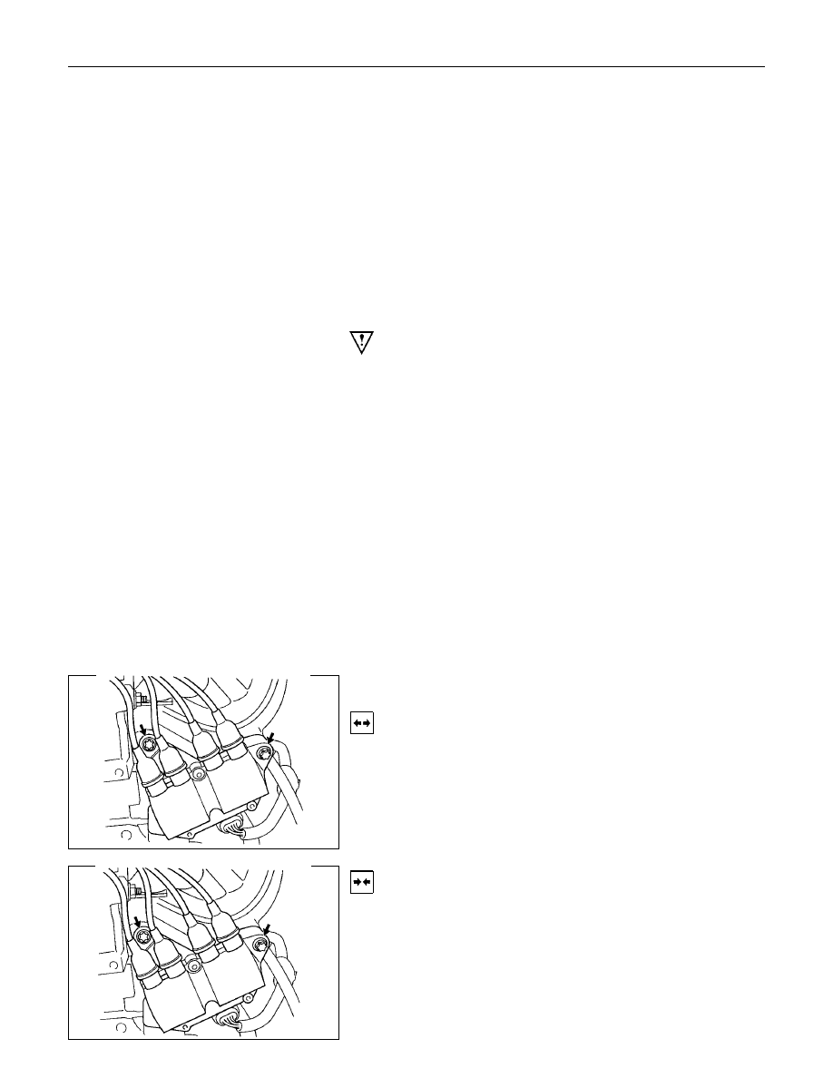
Ignition Coil
Removal
1. Disconnect battery ground cable.
2. Disconnect the Ignition coil connector.
3. Remove the ignition coil.
Installation
1. Install the ignition coil.
Connect ignition coil connector and ignition coil, then tighten
bolt to the specified torque.
Torque: 20 N
⋅⋅⋅⋅m (2.0 kgf⋅⋅⋅⋅m)
2. Connect battery ground cable.
Нет комментариевНе стесняйтесь поделиться с нами вашим ценным мнением.
Текст