Isuzu D-Max / Isuzu Rodeo (TFR/TFS). Manual — part 305

AUTOMATIC TRANSMISSION (AW30-40LE) 7A-69
DTC P0753 (FLASHING CODE 31) SOLENOID 1 FAILURE (S1)
Step Action
Value(s)
Yes
No
1
1. With the engine "OFF", turn the ignition
"ON".
2. Connect a voltmeter between the TCM 20
pin connector terminal (4) and ground
terminal (15 or 19).
Is the voltage within the specified value?
8-16 V
Go to Step 2
Go to Step 3
2
1. Lift the driving wheels and support them.
2. Turn the ignition "ON", and the engine "ON".
Can the speed be changed normally by
acceleration is the "NORMAL" mode and the D
range?
Go to Step 4
Go to Step 8
3
1. Turn the ignition "OFF".
2. Disconnect the TCM 20 pin connector.
3. Measure the resistance between the TCM 20
pin connector terminal (4) and ground.
Is the resistance within the specified value?
11-15
Ω (at 20°C)
Go to Step 5
Go to Step 6
4
At the 3rd speed gear.
Is the voltage between the TCM 20 pin connector
terminal (4) and ground terminal (15 or 19) less
than the specified value?
1 V
Go to Step 7
Go to Step 8
5
The TCM is faulty or the continuity of wiring
harness is intermittent.
Was a problem found and corrected?
Go to Step 13
6
Disconnect the A/T 8 pin connector.
Is the resistance between the solenoid S1
connector terminal (4) and ground within the
specified value?
11-15
Ω (at 20°C)
Go to Step 9
Go to Step 10
7
1. Clear the TCM memory.
2. Make a running test.
Is DTC P0753 displayed by self-diagnosis?
Go to Step 5
The continuity
of wiring is
intermittent.
Refer to
"Diagnostic
aids".
8
1. Turn the ignition "OFF".
2. Disconnect the TCM 20 pin connector.
3. Measure the resistance between the TCM 20
pin connector terminal (4) and ground.
Is the resistance within the specified value?
11-15
Ω (at 20°C)
Go to Step 5
Go to Step 11
9
Check the wiring harness between the TCM 20
pin connector terminal (4) and A/T 8 pin
connector terminal (4) for ground shorted.
Was a problem found and corrected?
Go to Step 13
10
Replace the solenoid S1.
Is the replacement complete?
Go to Step 13
11
1. Disconnect the A/T 8 pin connector.
2. Measure the resistance between the A/T 8
pin connector terminal (4) and ground.
Is the resistance within the specified value?
11-15
Ω (at 20°C)
Go to Step 12
Go to Step 10

7A-70 AUTOMATIC TRANSMISSION (AW30-40LE)
DTC P0753 (FLASHING CODE 31) SOLENOID 1 FAILURE (S1) (Cont’d)
Step Action
Value(s)
Yes
No
12
Check the wiring harness between the TCM 20
pin connector terminal (4) and A/T 8 pin
connector terminal (4) for open.
Was a problem found and corrected?
Go to Step 13
13
1. After the repair is complete, use the scan tool
to select "DTC", then "Clear Info" function.
2. Make a road running test for the vehicle.
3. Review the scan tool "DTC Info".
Has the last test failed or is the current DTC
displayed?
Begin the
diagnosis
again.
Go to Step 1
System OK
AUTOMATIC TRANSMISSION (AW30-40LE) 7A-71
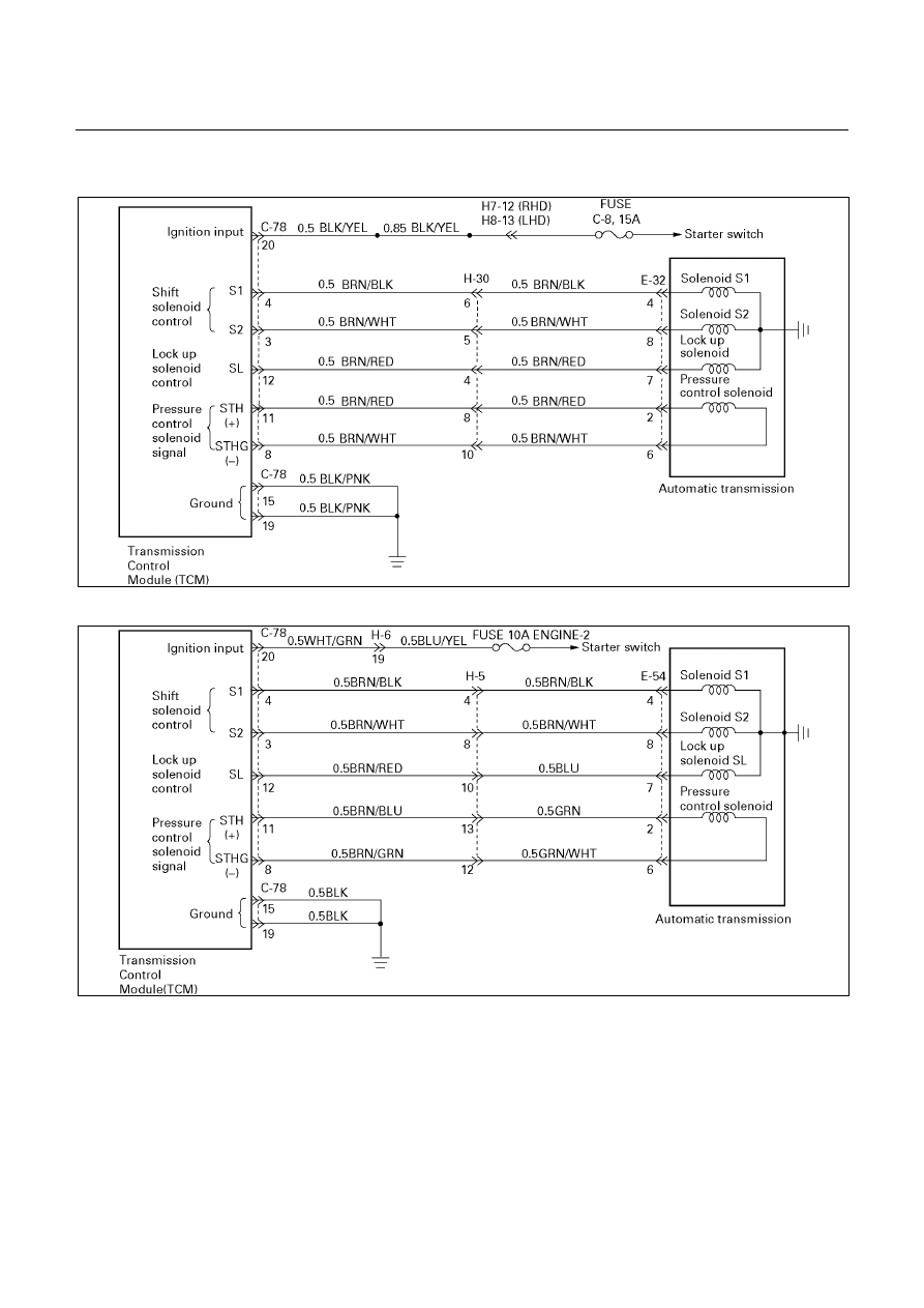
DTC P0758 (FLASHING CODE 32) SOLENOID 2 FAILURE (S2)
UBS (For General Export)
D07R200062
TFR/S (For Australia) and TFR (For South Africa)
D07L200007
7A-72 AUTOMATIC TRANSMISSION (AW30-40LE)
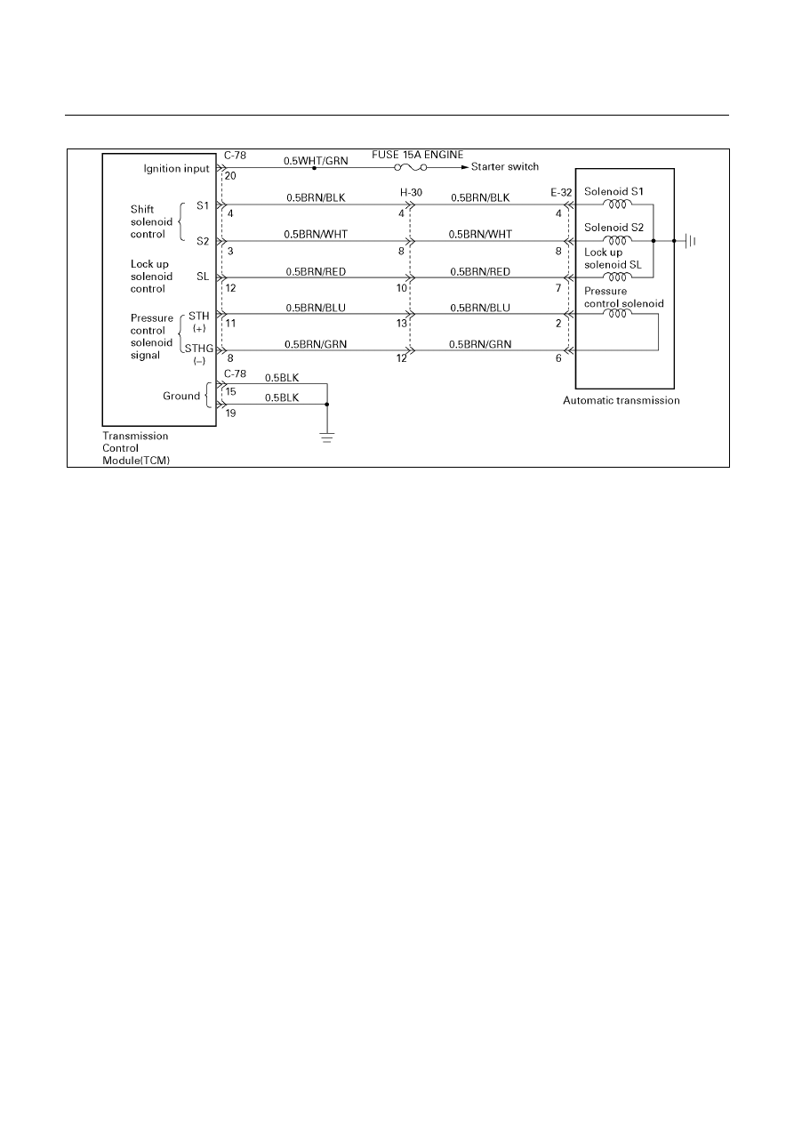
‘01TFR (For Thailand)
D07L100010
Circuit description:
The solenoid S2 changes the hydraulic route with the
signals from the TCM according to the vehicle speed
and the throttle opening to control shifting. When the
solenoid S1 or S2 fails, the hydraulic circuit is
mechanically operated as a backup.
Fail-safe control:
The TCM controls fail-safe by detecting S1, S2 shift
solenoid failure.
Failure detection:
GND SHORT detection
• When SHORT detection continues for 0.3 sec.
• When SHORT failure detection continues 8 times.
Open detection
• When OPEN detection continues for 0.5 sec.
• When OPEN failure detection continues 8 times.
Contents of control:
At failure detection
• Lock-up control inhibit
• Up hill and down hill control inhibit (For UBS)
• Squat control inhibit
• Changes solenoid output pattern as "The shift
theory at shift solenoid failure". (See DTC P0753)
At failure decision
• Executes following items in addition to above
control items at failure detection.
• Turns Solenoid power supply OFF
• Blinks "CHECK TRANS" lamp
• Stores the failure information in failure-memory
*Prohibits failure detection of S1, S2, SL, STH,
Selector position switch, and Oil temperature
sensor.
Conditions of turning "CHECK TRANS" off:
Turns "CHECK TRANS" lamp off after ignition is turned
ON
→ OFF→ ON.
Reversion conditions from fail-safe:
At failure detection
When a normal judgment is obtained by rechecking
during shifting.
At failure decision
Recovers at the same time as the conditions of
turning “CHECK TRANS” lamp off are satisfied.
Test description:
The following numbers correspond to the step numbers
on the diagnostic chart.
1. With the key "ON", the voltage between the TCM
20 pin connector terminals (3) or (15 or 19) is 1V or
less.
4. When the driving wheels revolve with the 2nd
speed gear, the voltage is 8 to 16V.
3.6.8.11. The resistance of the solenoid is in the range
of 11 to 15
Ω (at 20).
Diagnostic aids:
In case of faulty connection, open or shorted circuit to
the TCM 20 pin connector terminal (3), DTC P0758 is
displayed. A intermittent failure may be caused by a
poor connection, rubbed through wire insulation or a
wire broken inside the insulation.
Нет комментариевНе стесняйтесь поделиться с нами вашим ценным мнением.
Текст