Isuzu D-Max / Isuzu Rodeo (TFR/TFS). Manual — part 1865
7A2-76 DIAGNOSIS
Step
Action
Yes
No
8
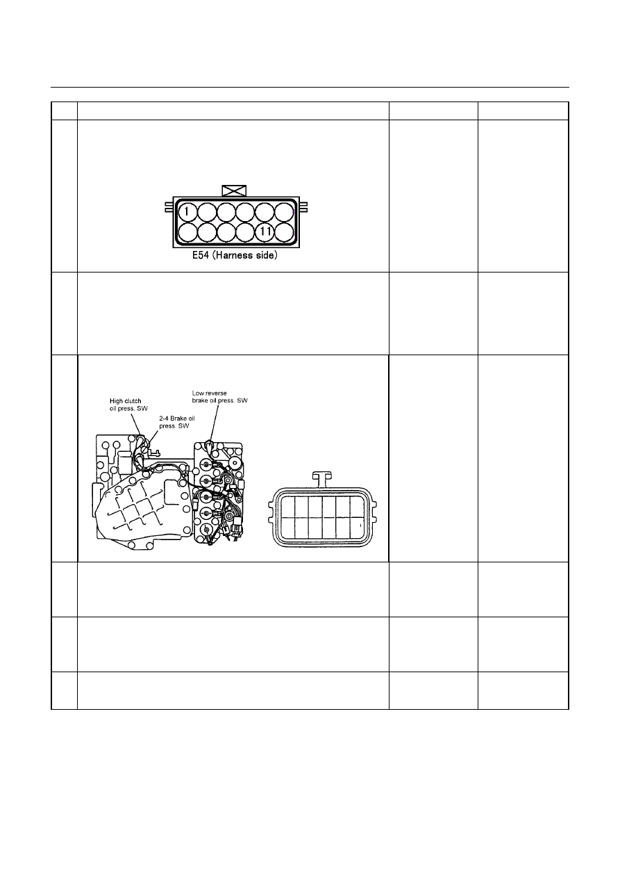
Connect the Tech 2, and with the key switch in OFF position, short
the terminals 11 and 1 on the vehicle harness side. Does the
indication of the high clutch pressure switch on the Tech 2 turn on
when the key switch is turned on?
Go to Step 9
Repair the harness
or connector.
Go to Step 12
9
Check if the trouble is caused by a poor connection of terminal
assembly connector.
With the key switch in OFF position, is the connection condition of
the connector and harness correct?
Go to Step 10
Repair the harness
or connector. Go to
Step 12
10 Remove the oil pan. Is the continuity correct between terminal
assembly teminal 1 and high clutch pressure switch connector?
1
Go to Step 11
Repair the harness
or connector.
Go to Step 12
11 Is the result OK when the oil pan is removed and the high clutch
pressure switch is checked?
Repair the control
valve.
Go to Step 12
Replace pressure
switch.
Go to Step 12
12 Clear the DTC from the memory and perform the work after repair.
Is the same DTC code outputted again in the subsequent DTC
check?
Replace the TCM
Go to Step 13
13 Are the other DTCs outputted?
Go to Other DTC
Section
Action is completed

DIAGNOSIS 7A2-77
DTC P0731 (Flash Code 41) 1st Gear Ratio Error
DTC P0732 (Flash Code 42) 2nd Gear Ratio Error
DTC P0733 (Flash Code 43) 3rd Gear Ratio Error
DTC P0734 (Flash Code 44) 4th Gear Ratio Error
Pre-setting Condition:
•
No
other
DTCs.
•
2 seconds elapsed after D, 3, 2, or 1 range was selected.
•
Vehicle is running at the vehicle speed over 10 km/h with the turbine speed over 1000 rpm.
•
Except at the gear shifting.
•
ATF temperature more than 60
°
C.
•
No fail safe valve malfunction.
Setting Condition:
In the case pre-setting conditions are met, the TCM calculates the turbine speed that corresponds to the gear ratio
of the outputted solenoid pattern in about 7 seconds after each gear shift has completed, and when the output shaft
speed against the turbine speed exceeds 500 rpm.
Fail Safe:
•
No fail safe function
Possible Cause:
•
Turbine sensor or speed sensor malfunction.
•
Shift
solenoid
malfunction.
•
Clutch
slipping.
Step
Action
Yes
No
1
Turn the key switch on and check the DTC. Are the DTC other
than gear ratio error outputted?
Go to Other DTC
Section
Go to Step 2
2
Clear the DTC from the memory. Turn the key switch off once,
and then start the engine. Does the CHECK TRANS blink
when the gear shift is repeated 3 times from 1st to 4th in the D
range?
Go to Other DTC
Section
Go to Step 3
3
Check again the DTC. Are all codes indicating gear ratio error
outputted?
Even if one of DTC
indicating gear ratio
error is outputted
Go to step 5
Go to Step 4
DTC indicating gear
ratio error are not
outputted at all.
Go to step 9
4
Check the turbine sensor and the speed sensor for function. Is
the result OK?
Go to Step 9
Replace turbine speed
sensor.
Go to Step 9
5
Are the color and smell of ATF normal?
Go to Step 6
Go to Step 9

7A2-78 DIAGNOSIS
Step
Action
Yes
No
6
Is the quantity of ATF correct?
Go to Step 7
Correct the quantity of
ATF.
Go to Step 9
7
Connect the Tech 2 and test the solenoids of respective
solenoids for low & reverse brake, 2-4 brake, high clutch and
low clutch. Is operation sound heard from each solenoid?
Go to Step 8
Replace the solenoid
that does not generate
the operation sound.
Go to Step 9
8
Check the line pressure during the idling and at the engine stall
speed. Is the line pressure correct?
Go to Step 10
Either control valve, oil
pump or power train
parts (clutch, brake)
will be faulty. Replace
or overhaul the
transmission unit.
Go to step 10
9
Run the vehicle, and is the gear shifted from 1st to 4th
correctly?
Go to Step 10
Either control valve, oil
pump or power train
parts (clutch, brake)
will be faulty. Replace
or overhaul the
transmission unit.
Go to step 10
10 Clear the DTC from the memory and perform the work after
repair. Is the same DTC code outputted again in the
subsequent DTC check?
Replace the TCM
Go to Step 11
11 Are the other DTCs outputted?
Go to Other DTC
Section
Action is completed
DIAGNOSIS 7A2-79
DTC P1750 (Flash Code 51) Low & Reverse Brake Fail-safe Valve Failure
Low & Reverse Brake Fail Valve (B)
Control Valve Upper Body
Low & Reverse Brake Fail Valve (A)
Control Valve Lower Body
Setting Condition:
•
When the oil pressure generated and low & reverse brake pressure switch operates off/on twice, the TCM
detected an operation failure of the low & reverse brake fail-safe valve in D, 3, 2, L range.
Fail Safe:
•
When the vehicle is running, the gear position selected at the trouble detection is held and the lock-up is
inhibited.
•
After the vehicle stopped, all solenoid operations stop (OFF) and the gear is fixed to the 3rd.
Possible Cause:
•
Stick of low & reverse brake fail-safe valve.
•
Low & reverse brake pressure switch does not turn on.
•
Short circuit to ground of harness low & reverse brake pressure switch.
•
Poor connection of each connector of harness in low & reverse brake pressure switch.
Нет комментариевНе стесняйтесь поделиться с нами вашим ценным мнением.
Текст