Isuzu D-Max / Isuzu Rodeo (TFR/TFS). Manual — part 1496
8-84 ELECTRICAL-BODY AND CHASSIS

ELECTRICAL-BODY AND CHASSIS 8-85
REMOVAL AND INSTALLATION
ECM (ENGINE CONTROL MODULE)
Removal
1. Remove the ECM.
Refer to the "ENGINE" Section of this Manual.
2. Loosen the three screws.
3. Pull out the ECM.
4. Disconnect both red and tan connectors.
Installation
Follow the removal procedure in the reverse order to install the
ECM.
Pay close attention to the important points mentioned in the
following paragraphs.
Connector
Be absolutely sure that ECM is securely connected.
This will prevent a poor contact and open circuit.
8-86 ELECTRICAL-BODY AND CHASSIS
REMOVAL AND INSTALLATION
FUEL PUMP
Removal
1. Remove the fuel tank.
Refer to the "ENGINE" Section of this Manual.
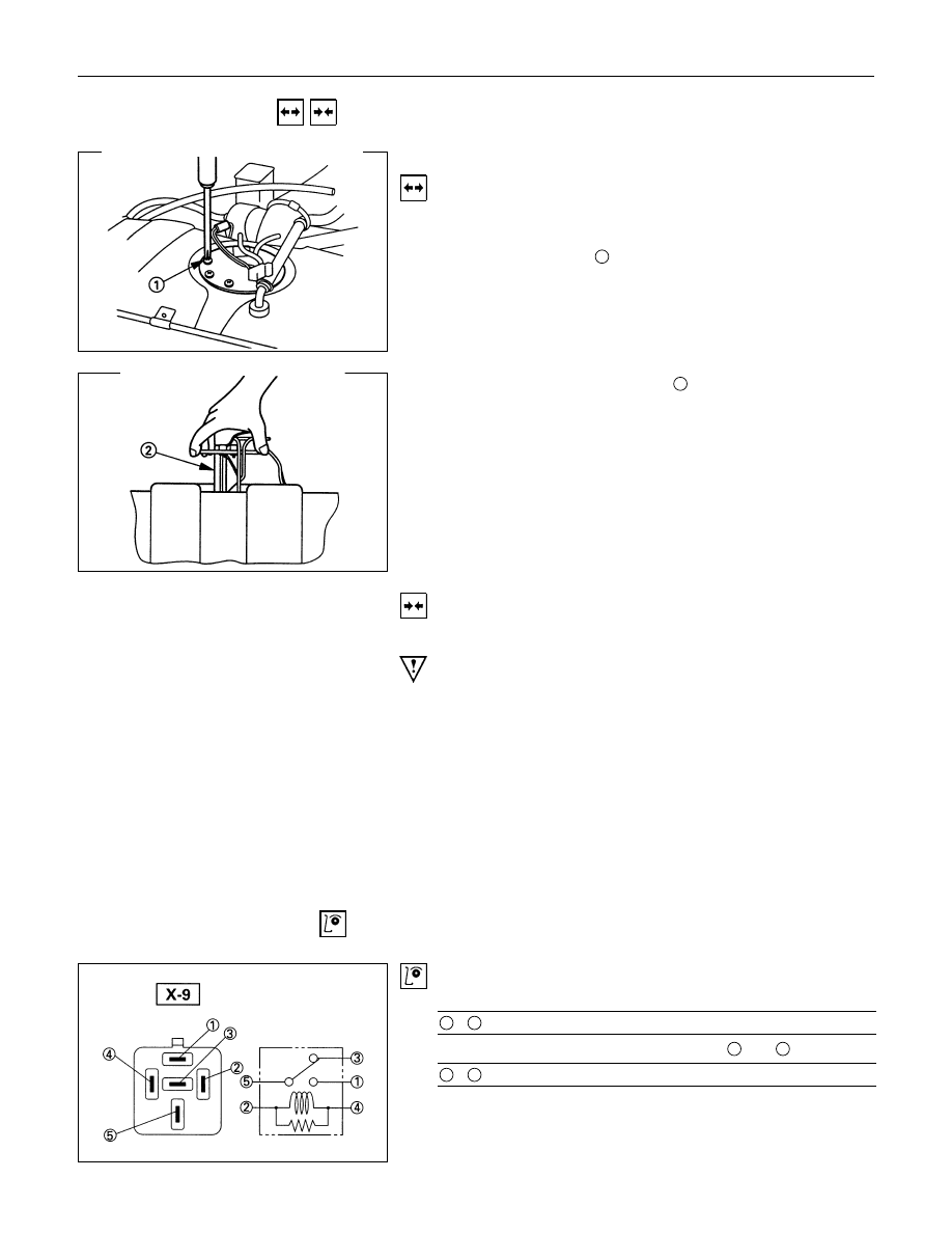
2. Loosen the screws
1
.
3. Raise the fuel pump assembly
2
from the fuel tank.
Installation
Follow the removal procedure in the reverse order to install the
fuel pump.
Pay close attention to the important points mentioned in the
following paragraphs.
Rubber Seal
Be absolutely sure that the fuel pump rubber seals correctly
seated.
Connector
Be absolutely sure that the fuel pump connector is securely
connected.
This will prevent a poor contact and an open circuit.
INSPECTION AND REPAIR
Fuel pump relay
Check continuity between the relay terminals.
1
-
5
. . . . . . . No continuity
(When battery voltage is applied between
2
and
4
)
1
-
5
. . . . . . . Continuity
ELECTRICAL-BODY AND CHASSIS 8-87
QOS/EGR/QWS
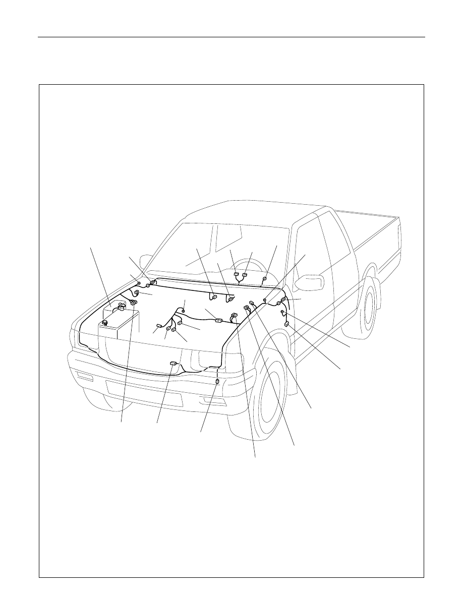
PARTS LOCATION (LHD)
RELAY & FUSE BOX
(X-5,X-8,X-14)
B-24
B-25
B-28
C-36
B-23
C-41
C-40
H-6
H-7
E-37
E-36
E-49
H-4
E-5
E-41
C-46
C-13
(4JG2)
C-14
C-15
(4JG2)
C-31
C-32
C-13
C-14
C-15
(4JA1)
C-28
C-23
H-8
C-2
C-49
C-50
Нет комментариевНе стесняйтесь поделиться с нами вашим ценным мнением.
Текст