Isuzu D-Max / Isuzu Rodeo (TFR/TFS). Manual — part 1546
8-284 ELECTRICAL-BODY AND CHASSIS
INSPECTION AND REPAIR
Harness side
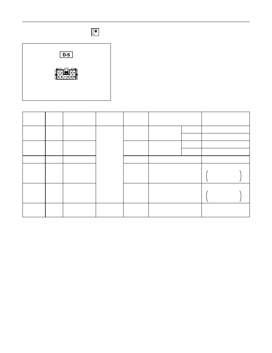
Driver Seat Side Power Window & Door Lock
Switch
1. Harness Side Connector Circuit
Check voltage and continuity between the switch harness
side connector terminals as shown in the following table.
Terminal
No.
Wire
color
Connecting to
Check item
Connecting
terminal
Check condition
Standard
Door lock SW
Driver seat
Lock
Continuity
(Lock)
side door
Unlock
No continuity
Door lock SW
Driver seat
Lock
No continuity
(Unlock)
side door
Unlock
Continuity
5
B
Ground
Continuity
5-Ground
-
Continuity
6
L/Y
Door lock
actuator (Lock)
(Resistance)
6-8
-
Continuity
There is some
resistance
8
Y/G
Door lock
actuator
(Unlock)
8-6
-
Continuity
There is some
resistance
9
LG/W
Fuse
CB-15 (20A)
Voltage
9- Ground
-
Battery voltage
(Approx. 12V)
3-Ground
R/W
3
4-Ground
LG/R
4
ELECTRICAL-BODY AND CHASSIS 8-285
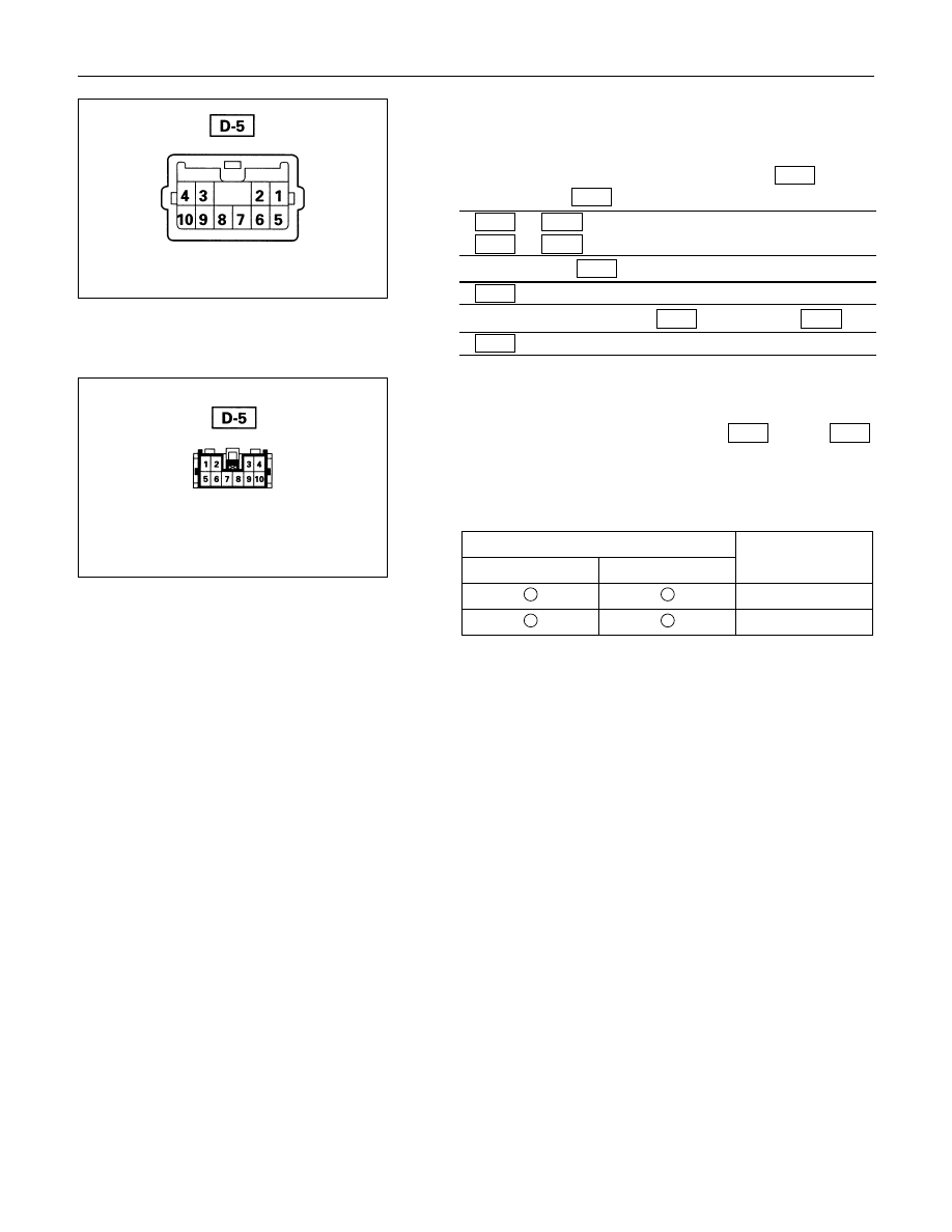
Switch side
2. Switch Side Connector Circuit
Remove the switch connector, and check continuity and
voltage between the switch connector terminals.
(Connect the (+) terminal of the battery to 9
D-5
and the
(-) terminal to 5
D-5
.)
5
D-5
- 6
D-5
. . . . .. Continuity
5
D-5
- 8
D-5
. . . . .. Continuity
(Then, ground 3
D-5
.)
6
D-5
. . ... Current flow for approx. 1 second
(Disconnect the ground of 3
D-5
, and ground 4
D-5
.)
8
D-5
. . ... Current flow for approx. 1 second
Harness side
3. Door Lock Operation Test
After confirming that there is continuity between the switch
harness side connector terminals 6
D-5
and 8
D-5
,
apply the battery voltage to each of the terminals to conduct
the operation test.
When the door lock will not operate, check the door lock
actuator for any trouble.
Connecting terminals
8 (Y/G)
6 (L/Y)
+
-
Unlock
-
+
Lock
Operation
8-286 ELECTRICAL-BODY AND CHASSIS
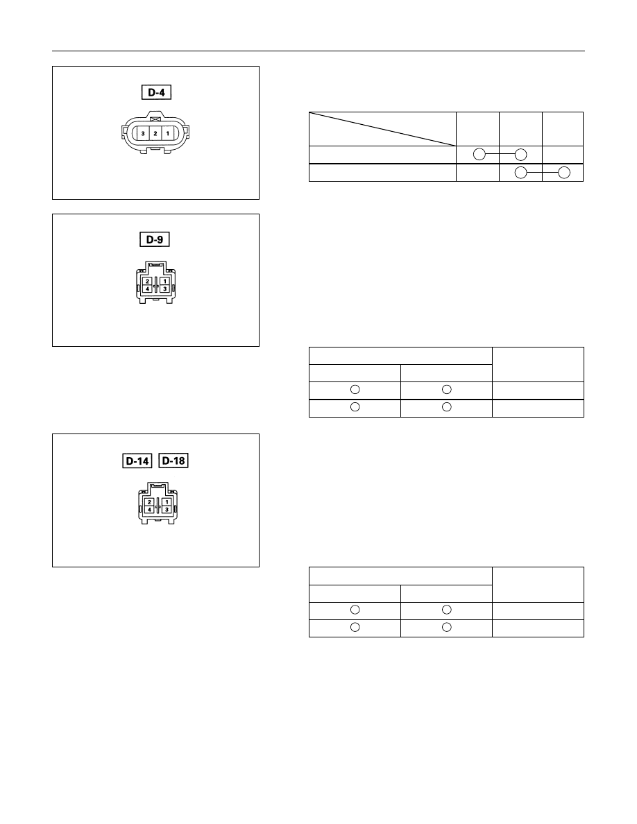
Switch side
Driver’s Side Door Lock Switch
1. Switch Side Connector Circuit
Check continuity between the switch connector terminals
Terminal No.
SW position
1
2
3
Lock
Unlock
Actuator side
Front Passenger’s Side Door Lock Actuator
1. Actuator Side Connector Circuit
Apply the battery voltage to the actuator connector terminals
to check the operation.
When the door lock actuator is checked on the vehicle and
there is no continuity, and when the door lock actuator itself
is checked and no trouble is found, check the circuit
between the door lock actuator and the driver seat side
power window & door lock switch for any failure.
Connecting terminals
2
4
+
-
Lock
-
+
Unlock
Operation
Actuator side
Rear Door Lock Actuator -LH & RH
1. Actuator Side Connector Circuit
Apply the battery voltage to the actuator connector terminals
to check the operation.
When the door lock actuator is checked on the vehicle and
there is no continuity, and when the door lock actuator itself
is checked and no trouble is found, check the circuit
between the door lock actuator and the driver seat side
power window & door lock switch for any failure.
Connecting terminals
1
3
-
+
Lock
+
-
Unlock
Operation

ELECTRICAL-BODY AND CHASSIS 8-287
POWER WINDOW
PARTS LOCATION (LHD)
Нет комментариевНе стесняйтесь поделиться с нами вашим ценным мнением.
Текст