Isuzu D-Max / Isuzu Rodeo (TFR/TFS). Manual — part 1862

7A2-64 DIAGNOSIS
•
Open circuit, short circuit to battery or short circuit to ground between lock-up duty solenoid terminal 4 and TCM
terminal B17 (C95).
•
Insufficient ground condition of the lock-up duty solenoid.
•
Poor connection of each connector.
Reference:
When the lock-up duty solenoid is operated, following signal is outputted.
Measurement terminal: B17 (C95) and B5 (C95)
-AC range by circuit tester: Approximately 7.2V
Lock-up Duty Solenoid Reference Wave Form
Measurement Terminal: B17 (+)
B5 (-)
Measurement Scale: 10V/div
5ms/div
Measurement Condition: Unlock-up condition
Lock-up Duty Solenoid Reference Wave Form
Measurement Terminal: B17 (+)
B5 (-)
Measurement Scale: 10V/div
5ms/div
Measurement Condition: Lock-up condition
DIAGNOSIS 7A2-65
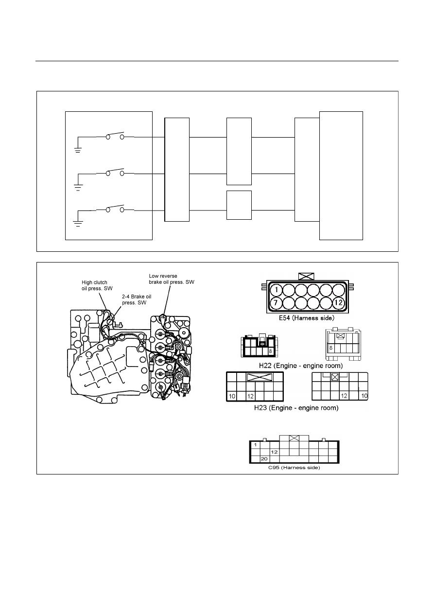
DTC P1853 (Flash Code 26) Low & Reverse Brake Pressure Switch Failure
Control Valve
TCM
B1
B12
B20
RED/YEL
WHT/BLK
2-4 Brake Pressure SW
Terminal
Assembly
YEL
E54
(7)
(12)
(1)
H23
(12)
(10)
C95
(1)
(12)
(20)
RED/YEL
YEL
WHT/BLK
L&R Brake Pressure SW
High Clutch Pressure SW
H22
(8)
Pre-setting Condition:
•
No gear shifting.
•
No Check Trans indicator lamp.
•
No system voltage failure.
•
No inhibitor switch failure.
•
Low & reverse brake duty solenoid 0 or 100 %.
•
ATF temperature more than 60
°
C.
•
ATF input voltage more than 0.1V.
•
Engine speed more than 500 rpm.
7A2-66 DIAGNOSIS
Setting Condition:
•
During the running, the low & reverse brake pressure switch does not turn on though hydraulic pressure is
supposed to be generated in the low & reverse brake.
(All pre-setting conditions are met for 2.5 seconds, Low & reverse brake duty solenoid 0% and low & reverse
brake pressure switch off in R range)
Or
•
During the running, the low & reverse brake switch does not turn off though no hydraulic pressure is supposed to
be generated in the low & reverse brake.
(All pre-setting conditions are met for 2.5 seconds, 4th gear, all pressure switch on and gear ratio 0.652 - 0.735
in D range.)
Fail Safe:
•
No fail safe function
Possible Cause:
•
Low & reverse brake duty solenoid malfunction.
•
Low & reverse brake pressure switch wire open circuit or short circuit.
•
Open circuit, short circuit to battery or short circuit to ground between low & reverse brake pressure switch
terminal 12 and TCM terminal B12 (C95).
•
Low & reverse brake hydraulic circuit malfunction in the control valve.
•
Poor connection of each connector.
Reference:
When the low & reverse brake pressure switch is operated, following signal is outputted.
Measurement terminal: B12 (C95) and B22 (C95)
-At other than R rage or L range in 1st gear: More than 10V
-At R range or L range in 1 st gear: Less than 1V
DIAGNOSIS 7A2-67
Step
Action
Yes
No
1
Clear the DTC from the memory once.
Was the action complete?
Go to Step 2
Refer DTC clear
method in this
manual.
2
Turn the ignition switch off once, then restart the engine and shift to
4th gear in the D range. When about 10 seconds elapsed, does the
CHECK TRANS lamp blink?
Go to Step 3
Go to Step 7
3
Is the DTC P0753 (31) Low & Reverse Brake Duty Solenoid Failure
stored?
Go to P0753 (31)
Section
Go to Step 4
4
Connect the Tech 2 and select the item for low & reverse brake
pressure switch. Is the indication of low & reverse brake pressure
switch turned off when the terminal assembly connector is
disconnected?
Go to Step 5
Repair the harness
or connector.
Go to Step 12
5
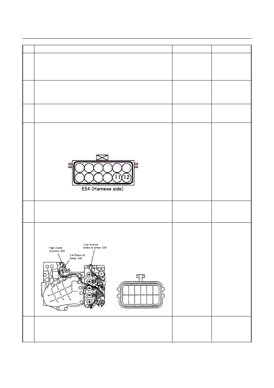
Turn the key switch off and disconnect the terminal assembly
connector. Are the pins correct?
Go to Step 6
Repair the
connector or pin.
Go to Step 12
6
Remove the oil pan. Is the continuity correct between terminal
assembly terminal 12 and low & reverse brake pressure switch
connector?
12
Repair the harness
or connector.
Go to Step 12
Replace pressure
switch.
Go to Step 12
7
Start the engine and select the R range. When about 10 seconds
elapsed, does the CHECK TRANS lamp blink?
Go to Step 8
Go to P0753 (31)
Section
Нет комментариевНе стесняйтесь поделиться с нами вашим ценным мнением.
Текст