Isuzu D-Max / Isuzu Rodeo (TFR/TFS). Manual — part 199

ENGINE DRIVEABILITY AND EMISSIONS
6E–37
J1-20
20
No Connection
-
-
-
-
-
-
-
-
-
J1-21
21
Crankshaft Position
(CKP) Sensor Signal
WHT -
-
Wave
form or
approx.
3.7V
Wave
form or
approx.
7.7V
Connect
AC V
21
6
J1-22
22
No.2 Injector
BLU/BLK
Less than
1V
Battery
voltage
Wave form
Connect
DC V
22
GND
J1-23
23
No Connection
-
-
-
-
-
-
-
-
-
J1-24
24
MAP Sensor Signal
GRY/RED
Less than
1V
Approx.
4.8V
Approx.
1.3V
Approx.
0.9V
Connect
DC V
24
16
J1-25
25
No Connection
-
-
-
-
-
-
-
-
-
J1-26
26
No Connection
-
-
-
-
-
-
-
-
-
J1-27
27
Engine Coolant Temp.
(ECT) Sensor Signal
GRY
Less than
1V
Approx. 2.5V at ECT 80°C
Connect
DC V
27
32
J1-28
28
Idle Air Control Valve
(IACV) Coil A High
YEL/BLK
Less than
1V
Less than 1V / Battery voltage
Connect
DC V
28
GND
J1-29
29
Idle Air Control Valve
(IACV) Coil B Low
YEL/GRN
Less than
1V
Less than 1V / Battery voltage
Connect
DC V
29
GND
J1-30
30
Idle Air Control Valve
(IACV) Coil A Low
BLU/WHT
Less than
1V
Less than 1V / Battery voltage
Connect
DC V
30
GND
J1-31
31
MAP Sensor Power
Supply
YEL/RED
Less than
1V
Approx.. 5V
Connect
DC V
31
16
J1-32
32
ECT Sensor, Knock
Sensor, Throttle
Position Sensor
Ground
BLU/PNK
Continuity
with
ground
-
-
-
Connect
Ω
32
GND
Pin
No.
B/Box
No.
Pin Function
Wire
Color
Signal or Continuity
ECM
Connection
Tester Position
Key SW
Off
Key SW
On
Engine
Idle
Engine
2000rpm
Range
(+)
(-)
6E–38
ENGINE DRIVEABILITY AND EMISSIONS
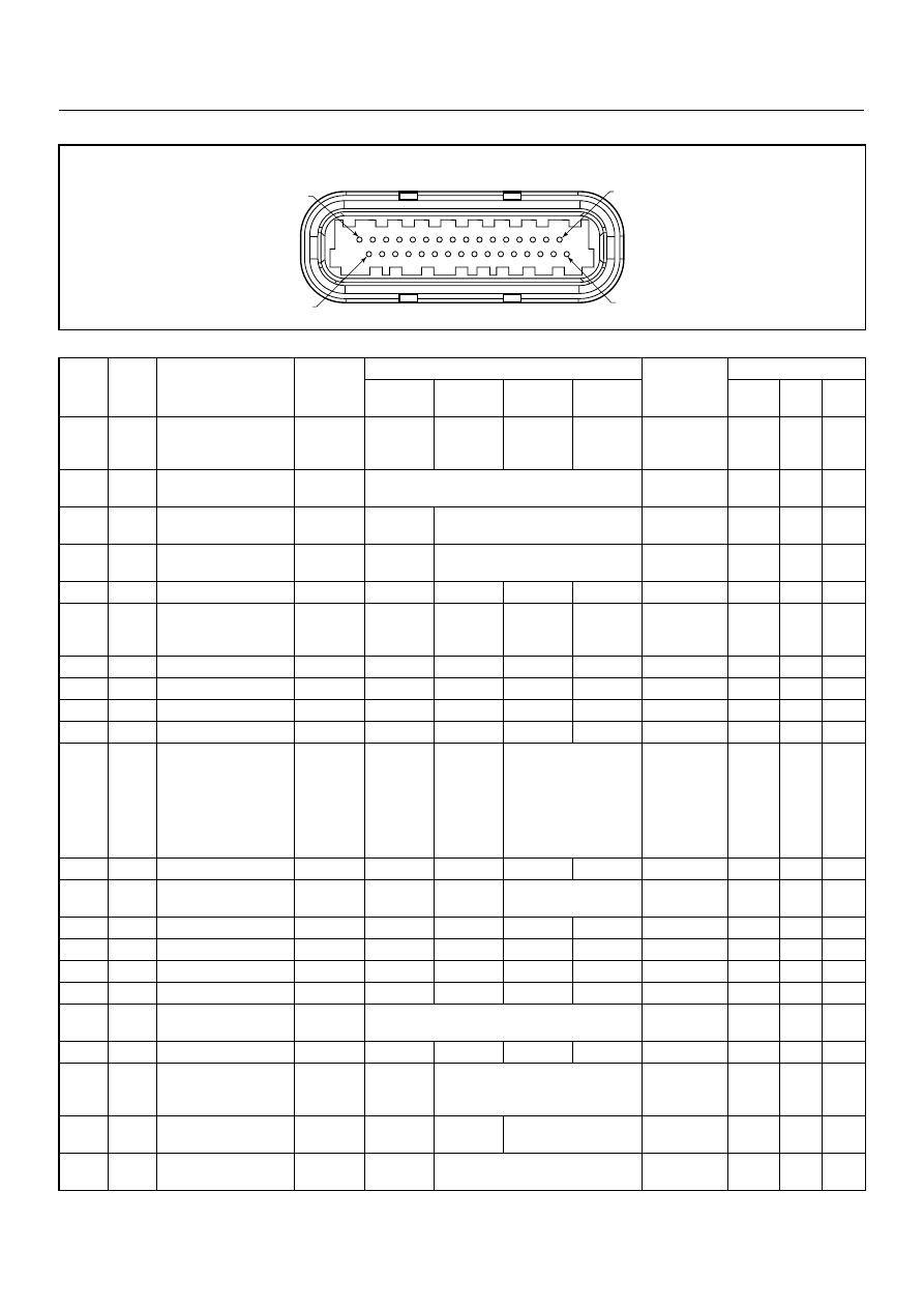
Connector J2 Port: View Looking Into ECM Case
1
17
16
32
PIN32
PIN1
PIN17
PIN16
Pin
No.
B/Box
No.
Pin Function
Wire
Color
Signal or Continuity
ECM
Connection
Tester Position
Key SW
Off
Key SW
On
Engine
Idle
Engine
2000rpm
Range
(+)
(-)
J2-1
33
Intake Air Temp. (IAT)
Sensor Ground
GRN
Continuity
with
ground
-
-
-
Disconnect
Ω
33
GND
J2-2
34
Battery Power Supply
RED/
WHT
Battery voltage
Connect
DC V
34
GND
J2-3
35
Ignition Power Supply
BLU/YEL
Less than
1V
Battery voltage
Connect
DC V
35
GND
J2-4
36
To Data Link
Connector No. 6
BLU Less
than
1V
Approx. 5V
Connect
DC V
36
GND
J2-5
37
No Connection
-
-
-
-
-
-
-
-
-
J2-6
38
Oxygen Sensor
(Ground)
PNK
Continuity
with
ground
-
-
-
Connect
Ω
38
GND
J2-7
39
No Connection
-
-
-
-
-
-
-
-
-
J2-8
40
No Connection
-
-
-
-
-
-
-
-
-
J2-9
41
No Connection
-
-
-
-
-
-
-
-
-
J2-10
42
No Connection
-
-
-
-
-
-
-
-
-
J2-11
43
Fuel Pump Relay
GRN/
WHT
Less than
1V
Less than
1V /
Battery
voltage
while fuel
pump is
activated
Battery voltage
Connect
DC V
43
GND
J2-12
44
No Connection
-
-
-
-
-
-
-
-
-
J2-13
45
A/C Compressor
Relay
GRY/RED
Less than
1V
Battery
voltage
Less than 1V
Connect
DC V
45
GND
J2-14
46
No Connection
-
-
-
-
-
-
-
-
-
J2-15
47
No Connection
-
-
-
-
-
-
-
-
-
J2-16
48
No Connection
-
-
-
-
-
-
-
-
-
J2-17
49
No Connection
-
-
-
-
-
-
-
-
-
J2-18
50
Battery Power Supply
RED/
WHT
Battery voltage
Connect
DC V
50
GND
J2-19
51
No Connection
-
-
-
-
-
-
-
-
-
J2-20
52
Power Steering
Pressure Switch
GRN/YEL
Less than
1V
Less than 1V when switch is turned
on / Battery voltage when switch is
turned off
Connect
DC V
52
GND
J2-21
53
Oxygen Sensor
BLU
Less than
1V
Approx.
0.4V
0.1 - 0.9V
Connect
DC V
53
38
J2-22
54
Intake Air Temp. (IAT)
Sensor (Signal)
YEL/GRN
Less than
1V
Approx. 1.8V at IAT 30°C
Connect
DC V
54
33

ENGINE DRIVEABILITY AND EMISSIONS
6E–39
J2-23
55
Vehicle Speed Signal
(Immobiliser Control
Unit Terminal B8)
WHT
-
-
Approx. 16Hz by wave
form or approx. 4.8V at
20km/h
Connect
AC V
55
GND
J2-24
56
No Connection
-
-
-
-
-
-
-
-
-
J2-25
57
Tachometer Output
Signal
BLK/RED
-
Wave form
-
-
-
-
J2-26
58
Thermo Relay
GRN/BLK
Less than
1V
Battery voltage when A/C request is
activated
Connect
DC V
58
GND
J2-27
59
No Connection
-
-
-
-
-
-
-
-
-
J2-28
60
No Connection
-
-
-
-
-
-
-
-
-
J2-29
61
No Connection
-
-
-
-
-
-
-
-
-
J2-30
62
To Data Link
Connector No. 2
GRN
-
-
-
-
-
-
-
-
J2-31
63
Oxygen Sensor Heater
BLU/WHT
Continuity
with
ground
-
-
-
Connect
Ω
63
GND
J2-32
64
Check Engine Lamp
(Immobiliser Control
Unit Terminal B7)
BRN/YEL
Less than
1V
Less than
1V
Battery voltage while
lamp is turned off
Connect
DC V
64
GND
Pin
No.
B/Box
No.
Pin Function
Wire
Color
Signal or Continuity
ECM
Connection
Tester Position
Key SW
Off
Key SW
On
Engine
Idle
Engine
2000rpm
Range
(+)
(-)
6E–40
ENGINE DRIVEABILITY AND EMISSIONS
GENERAL DESCRIPTION FOR ECM AND
SENSORS
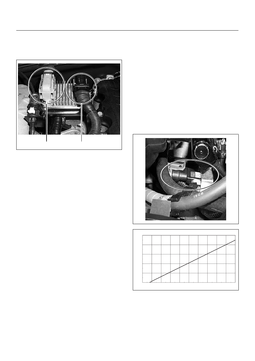
Engine Control Module (ECM)
The engine control module (ECM) is located on the
intake manifold. The ECM controls the following.
• Fuel metering system
• Ignition timing
• On-board diagnostics for electrical functions.
The ECM constantly observes the information from vari-
ous sensors. The ECM controls the systems that affect
vehicle performance. And it performs the diagnostic
function of the system.
The function can recognize operational problems, and
warn to the driver through the check engine lamp, and
store diagnostic trouble code (DTC). DTCs identify the
problem areas to aid the technician in marking repairs.
The input / output devices in the ECM include analog to
digital converts, signal buffers, counters and drivers.
The ECM controls most components with electronic
switches which complete a ground circuit when turned
on.
Inputs (Operating condition read):
• Battery voltage
• Electrical ignition
• Exhaust oxygen content
• Intake manifold pressure
• Intake air temperature
• Engine coolant temperature
• Crankshaft position
• Knock signal
• Throttle position
• Vehicle speed
• Power steering pressure
• Air conditioning request on or off
Outputs (Systems controlled):
• Ignition control
• Fuel control
• Idle air control
• Fuel pump
• EVAP canister purge
• Air conditioning
• Diagnostics functions
Manifold Absolute Pressure (MAP) Sensor
The MAP sensor is a strain gage. A pressure strains the
resistance on the silicon base. At that time the
resistance value changes. And it changes voltage. In
other words it measures a pressure value. It is installed
to the intake manifold. Output voltage of the MAP
sensor is low as pressure is low.
(1) J1 Port
(2) J2 Port
1
2
Output V
oltage
(V)
0
0
0.5
1
1.5
2
2.5
3
3.5
4
4.5
5
10
20
30
5
15
25
35
45
40
50 55
Pressure (KPa)
Characteristic of MAP Sensor (Reference)
60 65
75
70
85
80
90 95 100
Нет комментариевНе стесняйтесь поделиться с нами вашим ценным мнением.
Текст