Isuzu D-Max / Isuzu Rodeo (TFR/TFS). Manual — part 297

AUTOMATIC TRANSMISSION (AW30-40LE) 7A-37
DTC P0120 (FLASHING CODE 21)
ANALOG THROTTLE SIGNAL FAILURE (VTH) (FOR UBS)
Step Action
Value(s)
Yes
No
1
1. With the engine “OFF”, turn the ignition “ON”.
2. Connect a voltmeter between the TCM 28
pin connector terminal (6) and ground
terminal (28).
Is the voltage within the specified valve?
0.25−0.45 V
Go to Step 2
Go to Step 3
2
Open the throttle fully.
Is the voltage within the specified value?
3.74−4.56 V
The problem is
intermittent.
Refer to
“Diagnostic
aids”.
Go to Step 3
3
Connect a voltmeter between the ECM 32 pin
connector terminal (E1-6) and (E2-22).
Is the voltage within the specified value?
0.25−0.45 V
Go to Step 4
Go to Step 6
4
Open the throttle fully.
Is the voltage within the specified value?
3.74−4.56 V
Go to Step 5
Go to Step 6
5
1. Check the wiring harness between the TCM
28 pin connector terminal (6) and ECM 32
pin connector terminal (E1-6).
2. Or TCM is faulty.
Was a problem found and corrected?
−
Go to Step 9
−
6
1. Disconnect the TPS 3 pin connecter.
2. Connect a voltmeter between the TPS 3 pin
connector terminal (3) and (1).
Is the voltage within the specified value?
4.75−5.25 V
Go to Step 7
Go to Step 8
7
Check the TPS connector. If OK, replace the
TPS.
Is the replacement complete?
−
Go to Step 9
−
8
Check the wiring harness between the TPS and
ECM. If OK, replace the ECM.
Is the replacement complete?
−
Go to Step 9
−
9
1. After the repair is complete, use the scan tool
to select “DTC”, then “clear Info” function.
2. Make a road running test for the vehicle.
3. Review the scan tool “DTC Info”.
Has the last test failed or is the current DTC
displayed?
−
Begin the
diagnosis
again.
Go to Step 1
System OK
7A-38 AUTOMATIC TRANSMISSION (AW30-40LE)
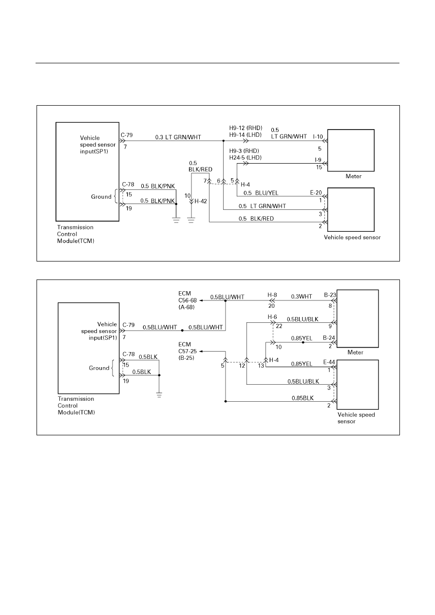
DTC P0502 (FLASHING CODE 24)
SPEED METER SENSOR FAILURE (SP1)
UBS (For General Export)
D07R200056
TFR/S (For Australia) and TFR (For South Africa)
D07L200001
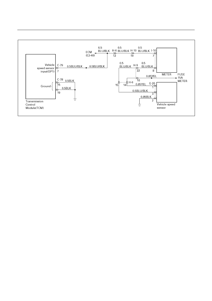
AUTOMATIC TRANSMISSION (AW30-40LE) 7A-39
’01 TFR (For Thailand)
D07L100004
Circuit description:
Speed information is provided by the speed meter
sensor to the meter.
In the meter, the pulses of the speed meter sensor are
converted to speed signals (pulses), and these signals
are output to the TCM and ECM(TF). The TCM
converts these pulse voltages to km/h signals.
Fail-safe control:
The TCM controls fail-safe by detecting speed meter
signal failure.
Failure detection:
• When the speed meter signal is not detected from
right after ignition turned ON:
When not even 1 pulse is input in the speed meter
signal during the time 100 pulses are input in the
output revolution sensor signal.
• When the speed meter signal is not detected, after
the speed meter signal is detected more than 1
pulse after ignition turned ON:
When not even 1 pulse is input in the speed meter
signal during the time 27 pulses are input in the
output revolution sensor signal.
Contents of control:
At failure detection
• Keeps the condition of transfer (High/Low
judgment) just before detection until vehicle speed
is 0km/h, and changes shift map to L4 map (3
→4
UP None) at vehicle speed is 0km/h. (For UBS)
• Uses high oil temperature map according to shift
map priority at correct oil temperature control.
• Up hill and down hill control inhibit. (For UBS)
• Stores the failure information in failure -memory.
• The failure detection of oil temperature sensor
inhibit
At failure decision
Executes following items in adition to above control
items at failure detection.
• Blinks "CHECK TRANS" lamp
Conditions of turning "CHECK TRANS" lamp
off:
Turns "CHECK TRANS" lamp off when judged 0km/h
by speed meter sensor after more than 1 pulse are
input in the speed meter signal during the time 27
pulses are input in the output revolution sensor.
Reversion conditions from fail-safe:
At failure detection and decision
Recovers at the same time as the conditions of turning
“CHECK TRANS” lamp off are satisfied.
Test description:
The following numbers correspond to the step numbers
on the diagnostic chart.
2. The cause of DTC P0502 setting is due to the
operation fault of the speed meter.
3. Speed signals are output from the meter. The
sensor power supply is given from the TCM.
Diagnostic aids:
An intermittent may be caused by a poor connection,
rubbed through wire insulation or a wire broken inside
the insulation. Inspect related harness connector for
backed out terminals, improper mating, broken locks,
improperly formed or damaged terminals, poor terminal
to wire connection and damaged harness.

7A-40 AUTOMATIC TRANSMISSION (AW30-40LE)
DTC P0502 (FLASHING CODE 24)
SPEED METER SENSOR FAILURE (SP1)
Step Action
Value(s)
Yes
No
1
1. Lift the driving wheels.
2. With the engine idling in gear D range.
Is the Tech 2 displayed speed the specified
value?
0 km/h
Go to Step 2
DTC P0502 is
intermittent.
If other DTCs
are not stored
in memory.
Refer to
“Diagnostic
aids”.
2
Does the speed meter operate?
−
Go to Step 3
Go to Step 4
3
1. Open the throttle and increase the revolution
speed of the driving wheels
2. Measure the voltage between the TCM 28
pin connector terminal (7) and TCM 20 pin
connector ground terminal (15 or 19) with a
voltmeter.
Does the voltage vary intermittently in the
specified value?
Less than 1.4 V ⇔
Greater than 9 V
(Pulse check)
(Vehicle speed 1∼
2 km/h)
Go to Step 5
Go to Step 6
4
The speed meter or speed meter sensor is
faulty.
Was a problem found and corrected?
−
Go to Step 7
−
5
The TCM connect is faulty or the TCM is faulty.
Was a problem found and corrected?
−
Go to Step 7
−
6
The wiring harness between the speed meter
and TCM is open or the speed meter sensor is
faulty.
Was a problem found and corrected?
−
Go to Step 7
−
7
1. After the repair is complete, use the scan tool
to select “DTC”, then “Clear Info” function.
2. Make the road running test for the vehicle.
3. Review the scan tool “DTC Info”.
Has the last test failed or is the current DTC
displayed?
−
Begin the
diagnosis
again.
Go to Step 1
System OK
Нет комментариевНе стесняйтесь поделиться с нами вашим ценным мнением.
Текст