Isuzu D-Max / Isuzu Rodeo (TFR/TFS). Manual — part 71
4JA1-TC/4JH1-TC ENGINE DRIVEABILITY AND EMISSIONS
6E–279
DIAGNOSTIC TROUBLE CODE (DTC) P1577 (SYMPTOM CODE 4)
(FLASH CODE 71) EXHAUST THROTTLE VSV 2 CIRCUIT VOLTAGE LOW
DIAGNOSTIC TROUBLE CODE (DTC) P1577 (SYMPTOM CODE 8)
(FLASH CODE 71) EXHAUST THROTTLE VSV 2 CIRCUIT VOLTAGE HIGH
Condition for setting the DTC and action taken when the DTC sets
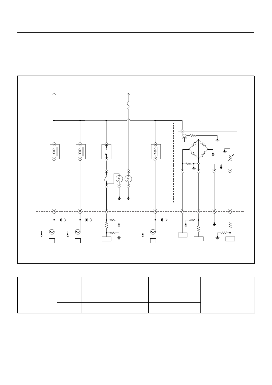
Circuit Description
The switch engine warming signals the engine control
module (ECM) to activate the quick warm-up system
(QWS).
Switch only provides the request and that the ECM
decides when to activated when certain conditions are
met.
If the exhaust throttle VSV 2 circuit is open or short
ground circuit, DTC P1577 (Symptom Code 4) is stored.
If the exhaust throttle VSV 2 circuit is short to voltage
circuit, DTC P1577 (Symptom Code 8) is stored.
Flash
Code
Code
Symptom
Code
MIL
DTC Name
DTC Setting Condition
Fail-Safe (Back Up)
71
P1577
4
ON
Exhaust Throttle VSV 2 Cir-
cuit Voltage Low
Exhaust throttle VSV 2 circuit
open or short to ground cir-
cuit.
No fail-safe function.
8
ON
Exhaust Throttle VSV 2 Cir-
cuit Voltage High
Exhaust throttle VSV 2 circuit
short to voltage circuit.
Batt
µP
Batt
µP
Batt
µP
0.5
BLK/
URG
0.5
BRN/
RED
0.5
BLU/
RED
0.5
BLU/
RED
4JA1-TC
0.5
GRY/
YEL
97
46
61
0.5
WHT/
RED
83
0.5
GRN/
RED
88
0.5
BLK/
RED
92
0.5
BLK/
BLU
84
IAT
Sensor
MAF &
IAT
Sensor
Rr Fog
Light
10A
EGR-
EVRV
0.5
WHT/
BLK
0.5
BLU/
RED
0.5
WHT/
BLU
0.5
BLU/
RED
0.5
GRN/
RED
0.5
BLU/
RED
Exhaust
Throttle
VSV2
Exhaust
Throttle
VSV1
Engine
Warming Up
SW
Thermo
SW
2
4
5
3
1
Battery
Voltage
ECM
Main Relay
IC
IC
IC
CPU
Engine
Control
Module
(ECM)
40
6E–280
4JA1-TC/4JH1-TC ENGINE DRIVEABILITY AND EMISSIONS
Diagnostic Aids
An intermittent may be caused by the following:
• Poor connections.
• Misrouted harness.
• Rubbed through wire insulation.
• Broken wire inside the insulation.
Check for the following conditions:
• Poor connection at ECM-Inspect harness connectors
for backed out terminals, improper mating, broken
locks, improperly formed or damaged terminals, and
poor terminal to wire connection.
• Damaged harness-Inspect the wiring harness for
damage. If the harness appears to be OK, observe
the DTC P1577 display on the Tech2 while moving
connectors and wiring harnesses.
Diagnostic Trouble Code (DTC) P1577 (Symptom Code 4) (Flash Code 71)
Exhaust Throttle VSV 2 Circuit Voltage Low
Step
Action
Value(s)
Yes
No
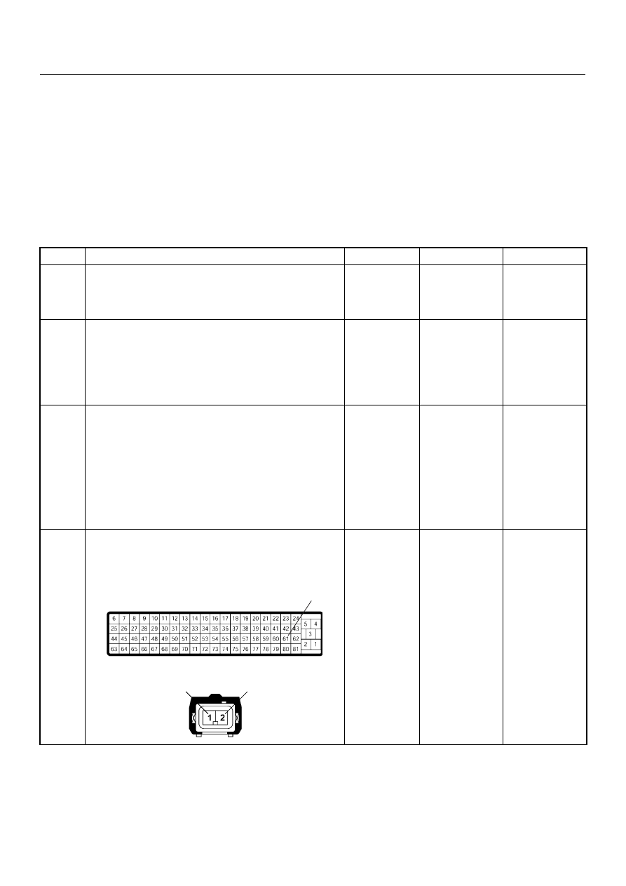
1
Was the “On-Board Diagnostic (OBD) System Check”
performed?
—
Go to Step 2
Go to On Board
Diagnostic
(OBD) System
Check
2
1. Connect the Tech 2.
2. Review and record the failure information.
3. Select “F0: Read DTC Infor As Stored By ECU” in
“F0: Diagnostic Trouble Codes”.
Is the DTC P1577 (Symptom Code 4) stored as
“Present Failure”?
—
Go to Step 3
Refer to
Diagnostic Aids
and Go to Step
3
3
1. Using the Tech 2, ignition “On” and engine “Off”.
2. Select “F1: Clear DTC Information” in “F0:
Diagnostic Trouble Codes” with the Tech 2 and
clear the DTC information.
3. Operate the vehicle and monitor the “F0: Read
DTC Infor As Stored By ECU” in the “F0:
Diagnostic Trouble Codes”.
Was the DTC P1577 (Symptom Code 4) stored in this
ignition cycle?
—
Go to Step 4
Refer to
Diagnostic Aids
and Go to Step
4
4
Check for poor/faulty connection at the exhaust
throttle VSV 2 or ECM connector. If a poor/faulty
connection is found, repair as necessary.
Was the problem found?
—
Verify repair
Go to Step 5
61
2
1
C-14
C-56
4JA1-TC/4JH1-TC ENGINE DRIVEABILITY AND EMISSIONS
6E–281
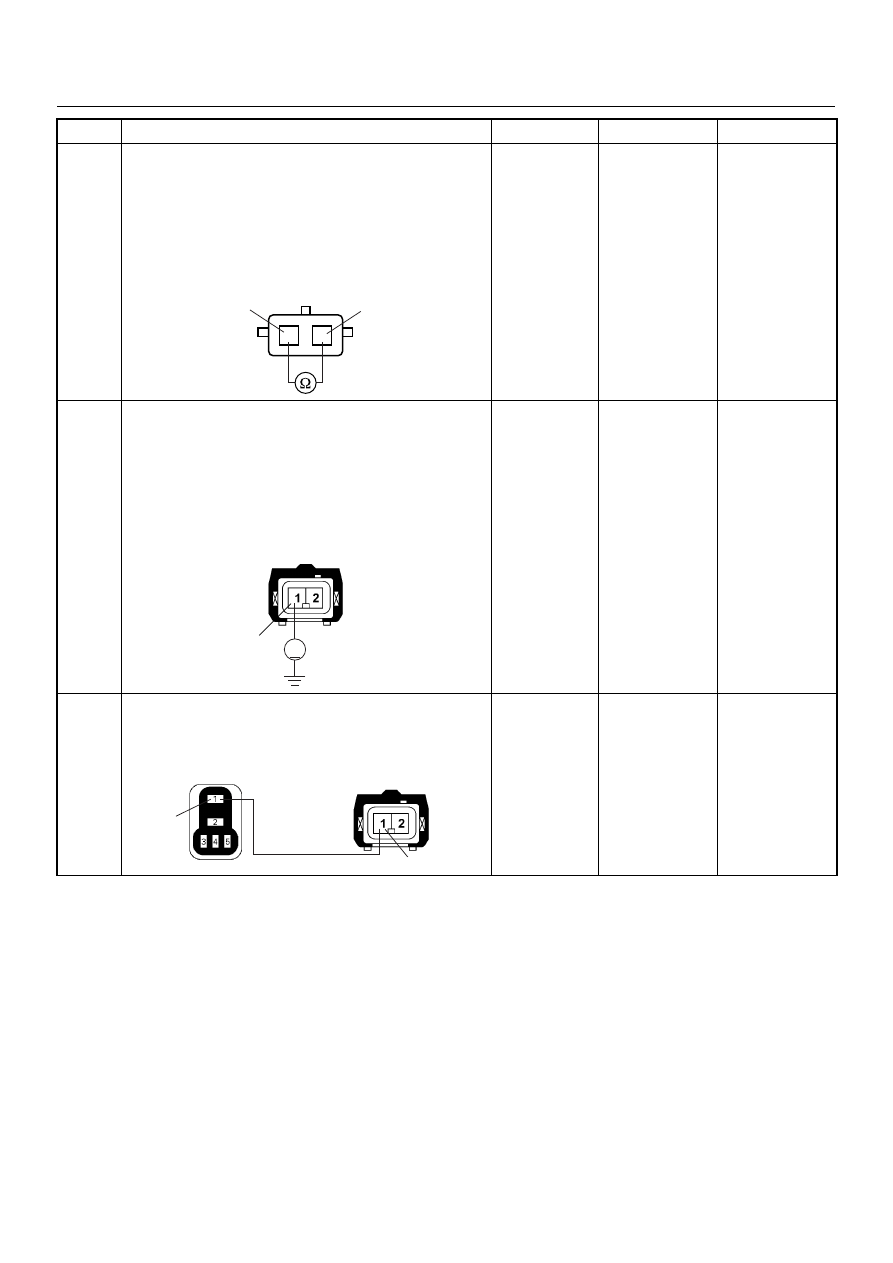
5
Using the DVM and check the exhaust throttle VSV 2.
1. Ignition “Off”, engine “Off”.
2. Disconnect the exhaust throttle VSV 2 connector.
3. Measure the resistance of exhaust throttle VSV 2
solenoid coil.
Does the tester indicate standard resistance?
Approximately
40
Ω at 20°C
Go to Step 6
Go to Step 9
6
Using the DVM and check the exhaust throttle VSV 2
power supply circuit.
1. Ignition “On”, engine “Off”.
2. Remove the exhaust throttle VSV 2 connector.
3. Check the circuit for open circuit.
Was the DVM indicated specified value?
Battery
voltage
Go to Step 8
Go to Step 7
7
Repair the open circuit between the ECM main relay
and exhaust throttle VSV 2.
Is the action complete?
—
Verify repair
—
Step
Action
Value(s)
Yes
No
1
2
1
2
VSV-2
V
1
C-14
1
1
X-4
C-14
6E–282
4JA1-TC/4JH1-TC ENGINE DRIVEABILITY AND EMISSIONS
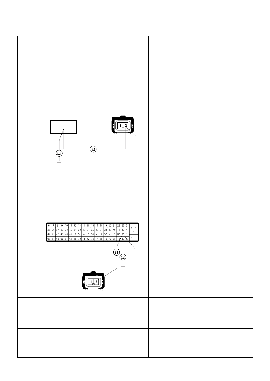
8
Using the DVM and check the exhaust throttle VSV 2
circuit.
Breaker box is available:
1. Ignition “Off”, engine “Off”.
2. Install the breaker box as type A. (ECM
disconnected) Ref. Page 6E-81
3. Remove the exhaust throttle VSV 2 connector.
4. Check the circuit for open or short to ground
circuit.
Was the problem found?
Breaker box is not available:
1. Ignition “Off”, engine “Off”.
2. Disconnect the ECM connector.
3. Remove the exhaust throttle VSV 2 connector.
4. Check the circuit for open or short to ground
circuit.
Was the problem found?
—
Repair faulty
harness and
verify repair
Go to Step 11
9
Substitute a known good exhaust throttle VSV 2 and
recheck.
Was the problem solved?
—
Go to Step 10
Go to Step 11
10
Replace the exhaust throttle VSV 2.
Is the action complete?
—
Verify repair
—
11
Is the ECM programmed with the latest software
release?
If not, download the latest software to the ECM using
the “SPS (Service Programming System)”.
Was the problem solved?
—
Verify repair
Go to Step 12
Step
Action
Value(s)
Yes
No
2
C-14
61
2
61
C-56
C-14
Нет комментариевНе стесняйтесь поделиться с нами вашим ценным мнением.
Текст