Isuzu D-Max / Isuzu Rodeo (TFR/TFS). Manual — part 109
6E–40
4JH1 ENGINE DRIVEABILITY AND EMISSIONS
GENERAL DESCRIPTION FOR ECM AND
SENSORS
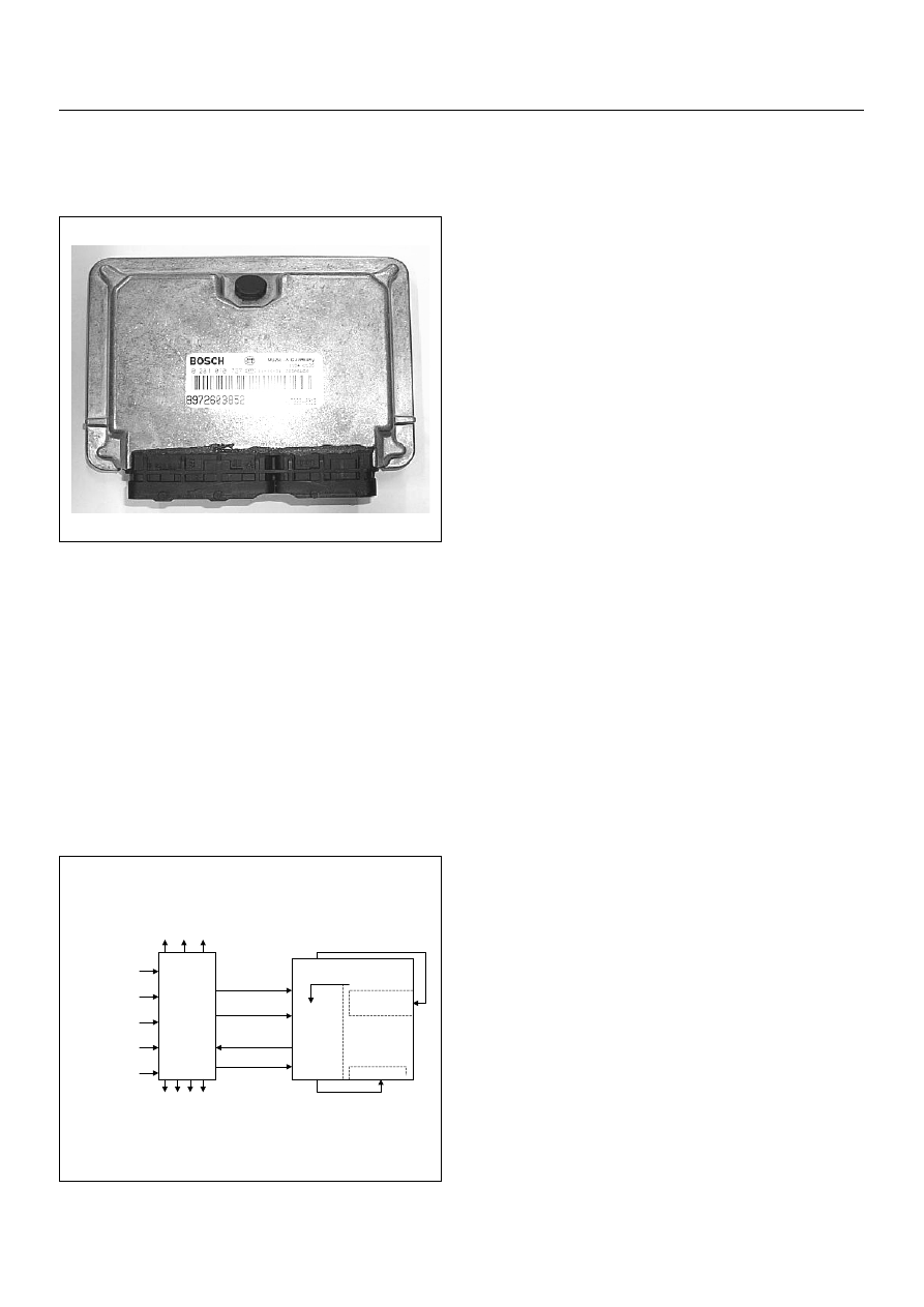
Engine Control Module (ECM)
The engine control module (ECM) is located flower
panel just under the passenger's seat.
The fuel quantity and injection timing related functions
are controlled by the pump control unit (PSG).
The engine control module (ECM) performs the
following functions.
• Control of the exhaust gas re-circulation (EGR)
• Control of the quick on start (QOS) glow control
system
• Control of the A/C compressor
• Execution of the immobiliser function
Pump Control Unit (PSG) & Data Exchange
Between Control Module
The radial plunger distributor type injection pump uses
two control modules to execute full control of the engine
management system.
• Engine Control Module (ECM)
• Pump Control Unit (PSG) = Pumpen Steuer Great
(German)
The pump control unit (PSG) receives signals from the
sensors inside the pump to determine the cam ring
rotation angle, the pump speed and the fuel
temperature .
These values are then compared to the desired values
sent by the engine control module (ECM) such as the
desired injection timing and the desired fuel injection
quantity.
The engine control module (ECM) processes all engine
data and data regarding the surrounding environment
received from external sensors to perform any engine
side adjustments.
Maps for both are encoded in both control units. The
control units input circuit process sensor data.
A Microprocessor then determines the operating
conditions and calculates set values for optimum
running.
The interchange of data between the engine control
module (ECM) and the pump control unit (PSG) is
perfumed via a CAN-bus system. The abbreviation CAN
stands for Controller Area Network. By having two
separate control modules, the high pressure solenoid
valve. This prevents the discharge of any disturbing
signals.
The following signals are exchanged via the CAN-bus:
From ECM to PSG
• Desired injection quantity
• Desired injection timing
• Engine speed
From PSG to ECM
• Fuel temperature
• Pump speed
• Cylinder identifier
• Control pulse (actual injection quantity + actual
injection timing)
• PSG status
Self Diagnosis / Interface / Signal
To High Pressure Solenoid
Engine Speed
Injection Timing
Accelerator Pedal
Injection Quantity
Intake Air Temperature
Response Signal
Mass Air Flow
Additional Signal
Others
Additional Operations To Timing Control Valve (TCV)
Engine
Control
Module
(ECM
Cam Ring Rotational Angle
Fuel Temperature
High Pressure
Solenoid Valve
Pump
Control Fuel Injection
Unit (Mechanical)
(PSG
Timing Device
4JH1 ENGINE DRIVEABILITY AND EMISSIONS
6E–41
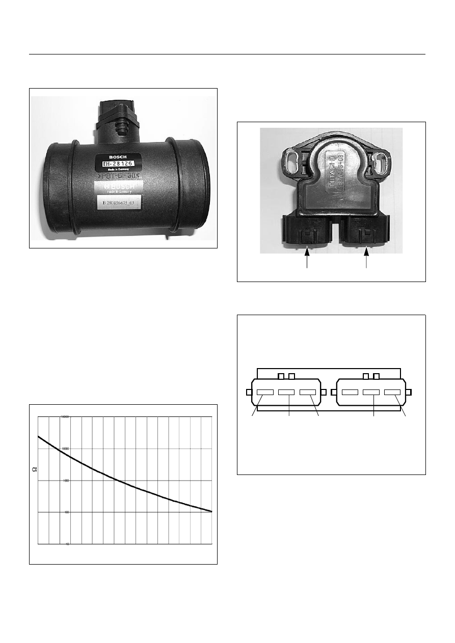
Mass Air Flow (MAF) Sensor & Intake Air
Temperature (IAT) Sensor
The mass air flow (MAF) sensor is part of the intake air
system.
It is fitted between the air cleaner and turbocharger and
measure the mass air flowing into the engine.
The mass air flow (MAF) sensor uses a hot film element
to determine the amount of air flowing into the engine.
The mass air flow (MAF) sensor assembly consist of a
mass air flow (MAF) sensor element and an intake air
temperature sensor that are both exposed to the air flow
to be measured.
The mass air flow (MAF) sensor element measures the
partial air mass through a measurement duct on the
sensor housing.
Using calibration, there is an extrapolation to the entire
mass air flow to the engine.
The IAT sensor is a thermistor. A temperature changes
the resistance value. And it changes voltage. In other
words it measures a temperature value. Low air
temperature produces a high resistance.
The ECM supplies 5 volts signal to the IAT sensor
through resisters in the ECM and measures the voltage.
The signal voltage will be high when the air temperature
is cold, and it will be low when the air temperature is hot.
Throttle Position Sensor (TPS)
-30 -20 -10
0
10
20
30
40
50
60
70
80
90
100 110 120 130
Characteristic of IAT Sensor
Temperature (
o
C)
Resistance ( )
(1) Throttle Position Sensor (TPS)
(2) Idle Switch
1
2
+5V
Output
Ground
+5V
Ground

6E–42
4JH1 ENGINE DRIVEABILITY AND EMISSIONS
The TPS is a potentiometer connected to throttle shaft
on the throttle body. It is installed to the main TPS and
idle switch.
The engine control module (ECM) monitors the voltage
on the signal line and calculates throttle position. As the
throttle valve angle is changed when accelerator pedal
moved. The TPS signal also changed at a moved
throttle valve. As the throttle valve opens, the output
increases so that the output voltage should be high.
The engine control module (ECM) calculates fuel
delivery based on throttle valve angle.
Crankshaft Position (CKP) Sensor
The CKP sensor is located on top of the flywheel
housing of the flywheel and fixed with a bolt.
The CKP sensor is of the magnet coil type. The
inductive pickup sensors four gaps in the flywheel
exciter ring and is used to determine the engine speed
and engine cylinder top dead center (TDC).
Engine Coolant Temperature (ECT) Sensor
The ECT sensor is a thermistor. A temperature changes
the resistance value. And it changes voltage. In other
words it measures a temperature value. It is installed on
the coolant stream. Low coolant temperature produces
a high resistance.
The ECM supplies 5 volts signal to the ECT sensor
through resisters in the ECM and measures the voltage.
The signal voltage will be high when the engine
temperature is cold, and it will be low when the engine
temperature is hot.
Characteristic of TPS
Throttle Angle (%)
Output V
oltage
(V)
(1) Engine Coolant Temperature (ECT) Sensor
(2) Thermo Unit for Water Temperature Gauge
1
2
-30
-20
-10
0
10
20
30
40
50
60
70
80
90
100 110 120
Characteristic of ECT Sensor
Temperature (deg. C)
Resistance ( )
4JH1 ENGINE DRIVEABILITY AND EMISSIONS
6E–43
Vehicle Speed Sensor (VSS)
M/T & A/T 4WD
A/T 2WD
The VSS is a magnet rotated by the transmission output
shaft. The VSS uses a hall element. It interacts with the
magnetic field treated by the rotating magnet. It outputs
pulse signal. The 12 volts operating supply from the
meter fuse.
The engine control module (ECM) calculates the vehicle
speed by VSS.
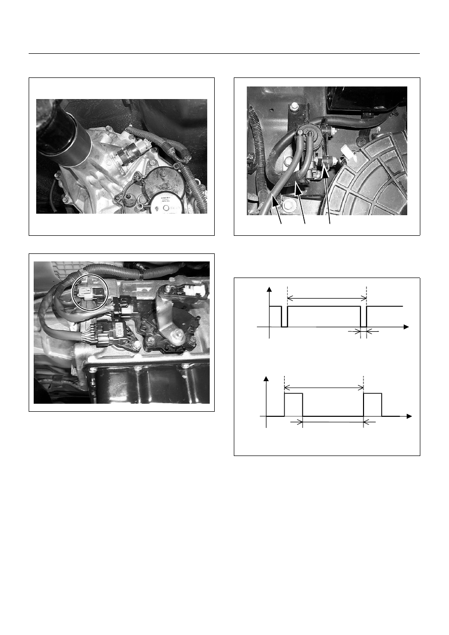
EGR EVRV
The EGR system on this engine is largely responsible
for a reduction of the NOx exhaust emission.
The amount of EGR is controlled by EVRV (electrical
vacuum regulating valve) via the engine control module
(ECM) command signal depends on the engine speed,
operating of the accelerator pedal and engine coolant
temperature.
The EVRV is shaped to control vacuum applied to the
diaphragm chamber of the EGR valve based on duty
signal sent from the ECM.
(1) EGR EVRV
(2) Connecting to Vacuum Pump
(3) Connecting to EGR Valve
3
2
1
7.1ms
Time
0.7ms
Vol
tage
Off duty 10% =EGR Pulse Ratio 10%
7.1ms
Time
Vol
tage
Off duty 70% =EGR Pulse Ratio 70%
6.4ms
Нет комментариевНе стесняйтесь поделиться с нами вашим ценным мнением.
Текст