Isuzu D-Max / Isuzu Rodeo (TFR/TFS). Manual — part 831
6E–53
3.2L ENGINE DRIVEABILITY AND EMISSIONS
No Malfunction Indicator Lamp (MIL)
060RW045
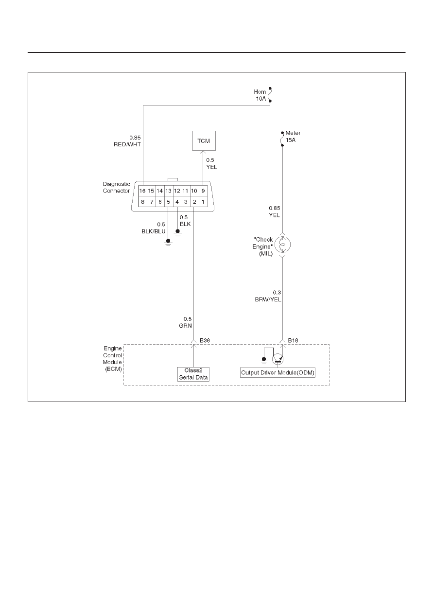
Circuit Description
The “Check Engine” lamp (MIL) should always be
illuminated and steady with the ignition “ON” and the
engine stopped. Ignition feed voltage is supplied to the
MIL bulb through the meter fuse. The Engine Control
Module ECM turns the MIL “ON” by grounding the MIL
driver circuit.
Diagnostic Aids
An intermittent MIL may be cased by a poor connection,
rubbed-through wire insulation, or a wire broken inside
the insulation. Check for the following items:
D
Inspect the ECM harness and connections for
improper mating, broken locks, improperly formed or
damaged terminals, poor terminal-to-wire connection,
and damaged harness.
D
If the engine runs OK, check for a faulty light bulb, an
open in the MIL driver circuit, or an open in the
instrument cluster ignition feed.
D
If the engine cranks but will not run, check for an open
ECM ignition or battery feed, or a poor ECM to engine
ground.
Test Description
Number(s) below refer to the step number(s) on the
Diagnostic Chart.
2. A “No MIL” condition accompanied by a no-start
condition suggests a faulty ECM ignition feed or
battery feed circuit.
9. Using a test light connected to B+, probe each of the
ECM ground terminals to ensure that a good ground
is present. Refer to
ECM Terminal End View for
terminal locations of the ECM ground circuits.
12.In this step, temporarily substitute a known good
relay for the ECM relay. The horn relay is nearby,
and it can be verified as “good” simply by honking
the horn. Replace the horn relay after completing
this step.

6E–54
3.2L ENGINE DRIVEABILITY AND EMISSIONS
No Malfunction Indicator Lamp (MIL)
Step
Action
Value(s)
Yes
No
1
Was the “On-Board Diagnostic (OBD) System Check”
performed?
—
Go to
Step 2
Go to
OBD
System
Check
2
Attempt to start the engine.
Does the engine start?
—
Go to
Step 3
Go to
Step 6
3
Check the meter fuse for the instrument cluster ignition
feed circuit.
Is the fuse OK?
—
Go to
Step 4
Go to
Step 16
4
Ignition “ON,” probe the ignition feed circuit at the
cluster connector with a test light to ground.
Is the test light “ON?”
—
Go to
Step 5
Go to
Step 13
5
1. Ignition “OFF.”
2. Disconnect the ECM.
3. Jumper the MIL driver circuit at the ECM connector
to ground.
4. Ignition “ON.”
Is the MIL “ON?”
—
Go to
Step 10
Go to
Step 11
6
Check the ECM ignition feed and battery feed fuses (15
A engine fuse and 15 A ECM fuse).
Are both fuses OK?
—
Go to
Step 7
Go to
Step 15
7
1. Ignition “OFF.”
2. Disconnect the ECM.
3. Ignition “ON.”
4. Probe the ignition feed circuit at the ECM harness
connector with a test light to ground.
Is the test light “ON?”
—
Go to
Step 8
Go to
Step 12
8
Probe the battery feed circuit at the ECM harness
connector with a test light to ground.
Is the test light “ON?”
—
Go to
Step 9
Go to
Step 14
9
Check for a faulty ECM ground connection.
Was a problem found?
—
Verify repair
Go to
Step 10
10
Check for damaged terminals at the ECM.
Was a problem found?
—
Verify repair
Go to
Step 17
11
Check for an open MIL driver circuit between the ECM
and the MIL.
Was a problem found?
—
Verify repair
Go to
Step 18
12
Substitute a known “good” relay for the ECM main
relay.
Was the malfunction fixed?
—
Verify repair
Go to
Step 13
13
Repair the open in the ignition feed circuit.
Is the action complete?
—
Verify repair
—
14
Locate and repair the open ECM battery feed circuit.
Is the action complete?
—
Verify repair
—
6E–55
3.2L ENGINE DRIVEABILITY AND EMISSIONS
No Malfunction Indicator Lamp (MIL)
(Cont'd)
Step
No
Yes
Value(s)
Action
15
Locate and repair the short to ground in the ECM
ignition feed circuit or ECM battery feed circuit.
Is the action complete?
—
Verify repair
—
16
Locate and repair the short to ground in the ignition
feed circuit to the instrument cluster, and replace the
fuse.
Is the action complete?
—
Verify repair
—
17
Replace the ECM.
Is the action complete?
—
Verify repair
—
18
Check the MIL driver circuit for a poor connection at the
instrument panel connector.
Was a problem found?
—
Verify repair
Go to
Instrument
Panel in
Electrical
Diagnosis

6E–56
3.2L ENGINE DRIVEABILITY AND EMISSIONS
Malfunction Indicator Lamp (MIL) “ON” Steady
060RW045
Circuit description
The “Check Engine” lamp (MIL) should always be
illuminated and steady with ignition “ON” and the engine
stopped. Ignition feed voltage is supplied directly to the
MIL indicator. The Engine Control Module ECM turns the
MIL “ON” by grounding the MIl driver circuit.
The MIL should not remain “ON” with the engine running
and no DTC(s) set. A steady MIl with the engine running
and no DTC(s) suggests a short to ground in the MIl driver
circuit.
Diagnostic Aids
An intermittent may be caused by a poor connection,
rubbed–through wire insulation, or a wire broken inside
the insulation. Check for the following items:
D
Poor connection or damaged harness – Inspect the
ECM harness and connectors for improper mating,
broken locks, improperly formed or damaged
terminals, poor terminal-to-wire connection, and
damaged harness.
Test Description
Number(s) below refer to the step number(s) on the
Diagnostic Chart.
2. If the MIL does not remain “ON” when the ECM is
disconnected, the MIL driver wiring is not faulty.
3. If the MIL driver circuit is OK, the instrument panel
cluster is faulty.
6. This vehicle is equipped with a ECM which utilizes
an electrically erasable programmable read only
memory (EEPROM).
Нет комментариевНе стесняйтесь поделиться с нами вашим ценным мнением.
Текст